System and method for safe well control operations

a well control and safety technology, applied in the direction of drilling pipes, wellbore/well accessories, sealing/packing, etc., can solve the problems of operator subsequently losing control of the well, difficulty in ensuring the successful completion of well control procedures, and loss of control of the well bore, so as to facilitate the operation of well control and facilitate hands-on training , the effect of improving accuracy

Active Publication Date: 2011-09-08
SAFEKICK AMERICAS LLC
View PDF8 Cites 77 Cited by
  • Summary
  • Abstract
  • Description
  • Claims
  • Application Information

AI Technical Summary

Benefits of technology

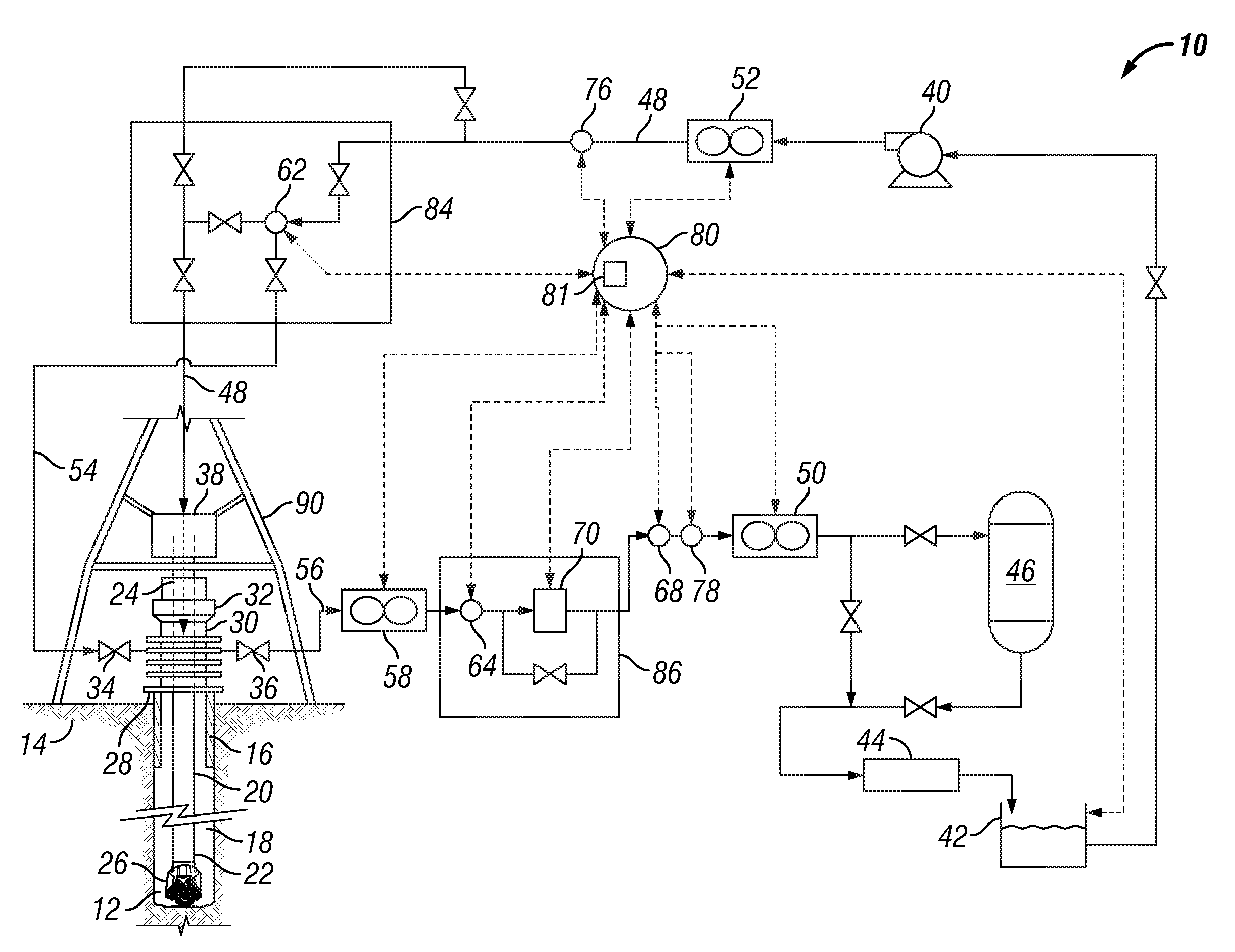
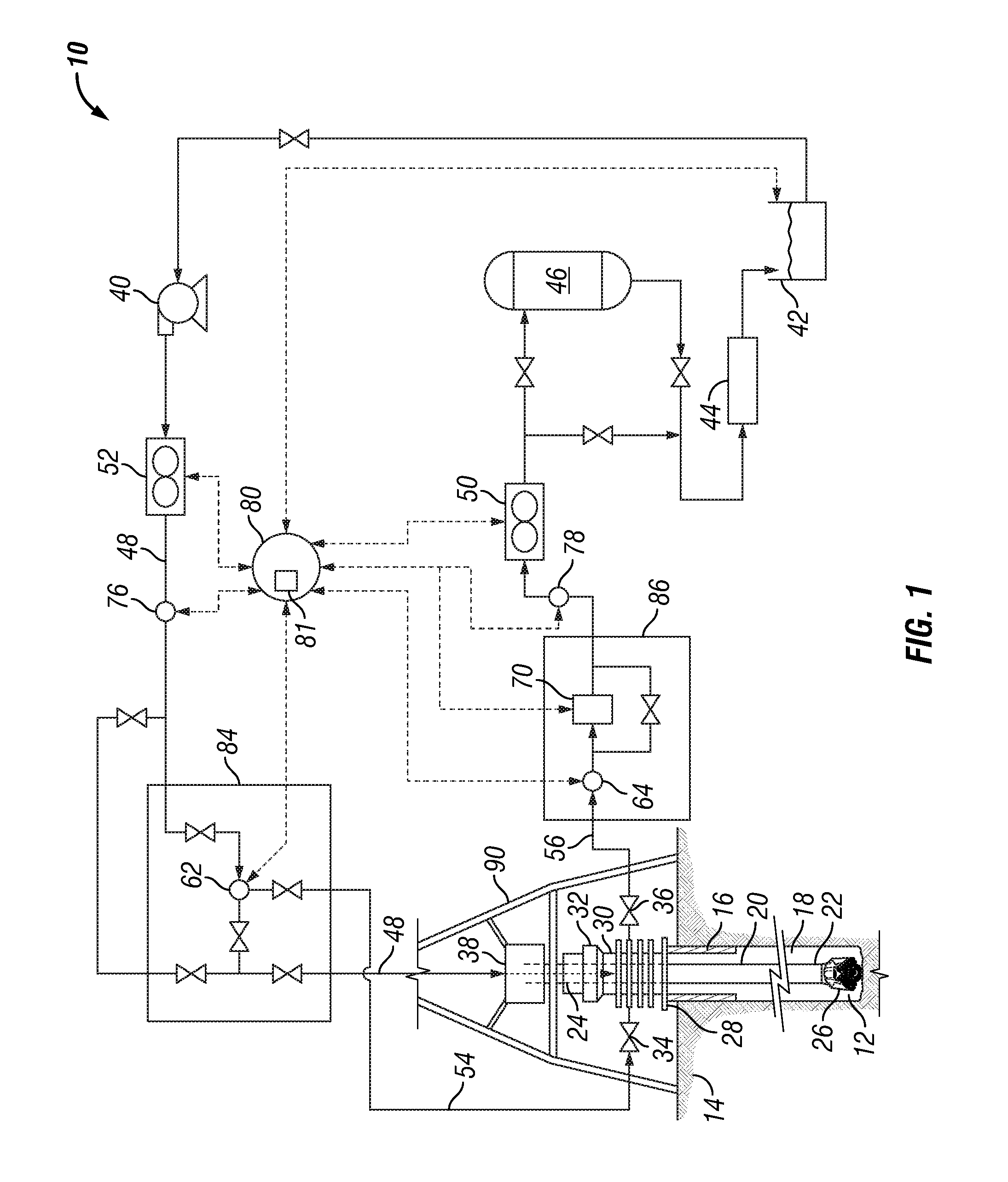
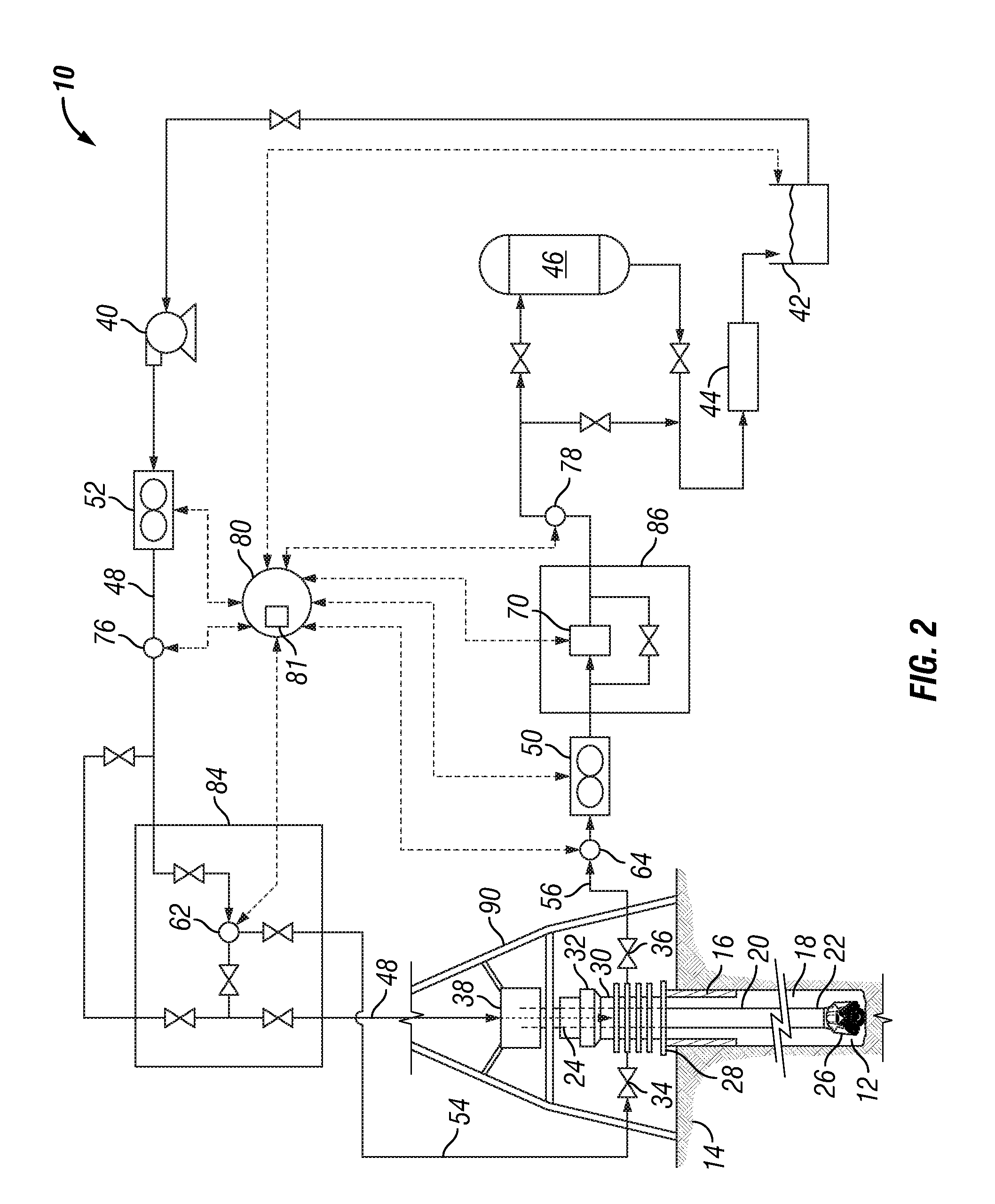
[0037]The measured fluid flow rates and fluid pressures permit the suspected fluid influx event to be confirmed and the pore and fracture pressures of the formation to be determined with greater accuracy, as further described herein. Based on the accurately determined pore and fracture pressures, the central control unit controls a flow control device disposed in the choke line to apply backpressure on the well so as to maintain the pressure inside the well bore between specified or conditional limits including, but not limited to, the pore pressure and the fracture pressure during the entire well control procedure. Confirming the suspected fluid influx and determining an accurate pore pressure also permit the correct fluid weight to be determine

Problems solved by technology

Such occurrence is an undesirable event and is known as taking a “kick.” This same situation can occur not only during drilling, but also during completion, work-over or intervention.
Under such circumstances, control of the well bore may be lost due to breach of the primary barrier.
The operator may subsequently lose control of the well, because the monitored and measured parameters are transient and confusing as a result of the previous kick.
Furthermore, it will be more difficult to ensure that the well control procedures were successfully completed and that the operator has effectively regained control of the well bore to permit recommencement of operations.
If the pressure inside the well bore oscillates too much during the circulation of the kick out of the well bore, then there is high risk that the pressure inside the well bore will fall below the formation pressure and a secondary kick will be taken while the process of controlling the first one is ongoing.
Alternatively, if the pressure inside the well bore oscillates and reaches the fracture pressure, fluid losses into the formation are induced.
This causes the integrity of the well bore to be severely jeopardized and makes the necessary well control operations much more difficult.
The Driller's method and the Wait and Weight method are only suitable, however, for use in commonly encountered well control situations.
In some cases, there is no margin to allow circulation of the influx without fracturing the formation.
These complex methods are more difficult to implement because several variables must be controlled, and this complexity is often more than the rig crew can handle.
Relying solely on pressure readings, however, does not allow the driller to completely understand downhole events, such as ascertaining the hydrostatically underbalanced condition based on the time the influx was taken, verifying that an influx indeed entered the well bore or ensuring that the well is under control.
Furthermore, using the pit volume as indicator of well condition during a well control method is far from accurate.
Current systems and methods for determining formation fracture pressure and formation pore pressure, however, are inaccurate.
For example, the pore pressure derived from stabilized surface standpipe and casing pressure readings measured after the BOP has been closed is often far from accurate, and in many cases, there is

Method used


Image

  • System and method for safe well control operations
  • System and method for safe well control operations
  • System and method for safe well control operations

Examples


example

[0072]The annulus pressure at a well bore depth of 10,000 feet in the well bore annulus between a 3 inch ID pipe and 5 inch ID pipe is to be determined. A Newtonian fluid having a density of 9.0 pounds per gallon is being circulated through the well bore at a flow rate of 100 gallons per minute. The backpressure being applied to the well bore annulus is 200 psi, as measured by the outlet pressure measurement device. The Θ300 rheological parameter of the fluid is 30 (i.e., μ=30 cp; the viscosity in centipoise). As previously discussed, the annulus pressure is determined by adding the hydrostatic pressure of the fluid / mud within the well bore annulus, the friction loss / pressure generated in the well bore annulus, and choke line if applicable, by any fluid in circulation, and the outlet pressure (i.e., backpressure applied to the well bore). The hydrostatic component of the annulus pressure is determined as the product of the equation, 0.052*(depth)*(density), which based on the above ...


PUM


Abstract

A system and method for safely controlling a well being drilled or that has been drilled into a subterranean formation in which a conventional blow-out preventer operates to close the well bore to atmosphere upon the detection of a fluid influx event. Fluid pressures as well as fluid flow rates into and out of the well bore are measured and monitored to more accurately and confidently determine the fracture pressure and pore pressure of the formation and perform well control operations in response to a fluid influx event. During a suspected fluid influx event, one or more of the fluid flow and pressure measurements are used to confirm the fluid influx event and to safely regain well control by circulating the fluid influx out of the well through a choke line while maintaining the pressure inside the well between specified, selected limits, such as between the fracture and pore pressures.

Description

CROSS REFERENCE TO RELATED APPLICATION[0001]This application is based on U.S. provisional patent application No. 61 / 311,166, filed on Mar. 5, 2010, the priority of which is claimed.BACKGROUND OF THE INVENTION[0002]1. Field of the Invention[0003]This invention relates generally to a system and method for the drilling, completion and work-over of oil and / or gas wells. Specifically, the invention relates to the control of oil and / or gas wells during the period when the blow-out preventer (BOP) is closed, or is in the process of being closed, due to events, such as kicks, that occur during drilling, completion, or while working over the well.[0004]2. Description of the Related Art[0005]During the drilling of subterranean wells, a fluid (“mud”) is typically circulated through a fluid circulation system comprising a drilling rig and fluid treating equipment located substantially at or near the surface of the well (i.e., earth surface for an on-shore well and water surface for an off-shore...

Claims


Application Information

Patent Timeline
IPC IPC(8): E21B33/06E21B34/06
CPCE21B21/08E21B44/00E21B21/10
Inventor SANTOS, HELIO
Owner SAFEKICK AMERICAS LLC
Why Eureka
Try Eureka