Biometric Sensor With Delay Layer

a delay layer and biometric sensor technology, applied in the field of ultrasonic reflex (i . e . reflected) imaging system, can solve the problem of reducing the clarity of the image that can be obtained

Active Publication Date: 2011-09-08
QUALCOMM INC
View PDF10 Cites 111 Cited by
  • Summary
  • Abstract
  • Description
  • Claims
  • Application Information

AI Technical Summary

Benefits of technology

[0009]Control electronics may be connected to the generator and to the detector. The control electronics may be able to manage timing of a generated ene

Problems solved by technology

It has been found that using the same device to generate and detect creates d

Method used


Image

  • Biometric Sensor With Delay Layer
  • Biometric Sensor With Delay Layer
  • Biometric Sensor With Delay Layer

Examples


Embodiment Construction

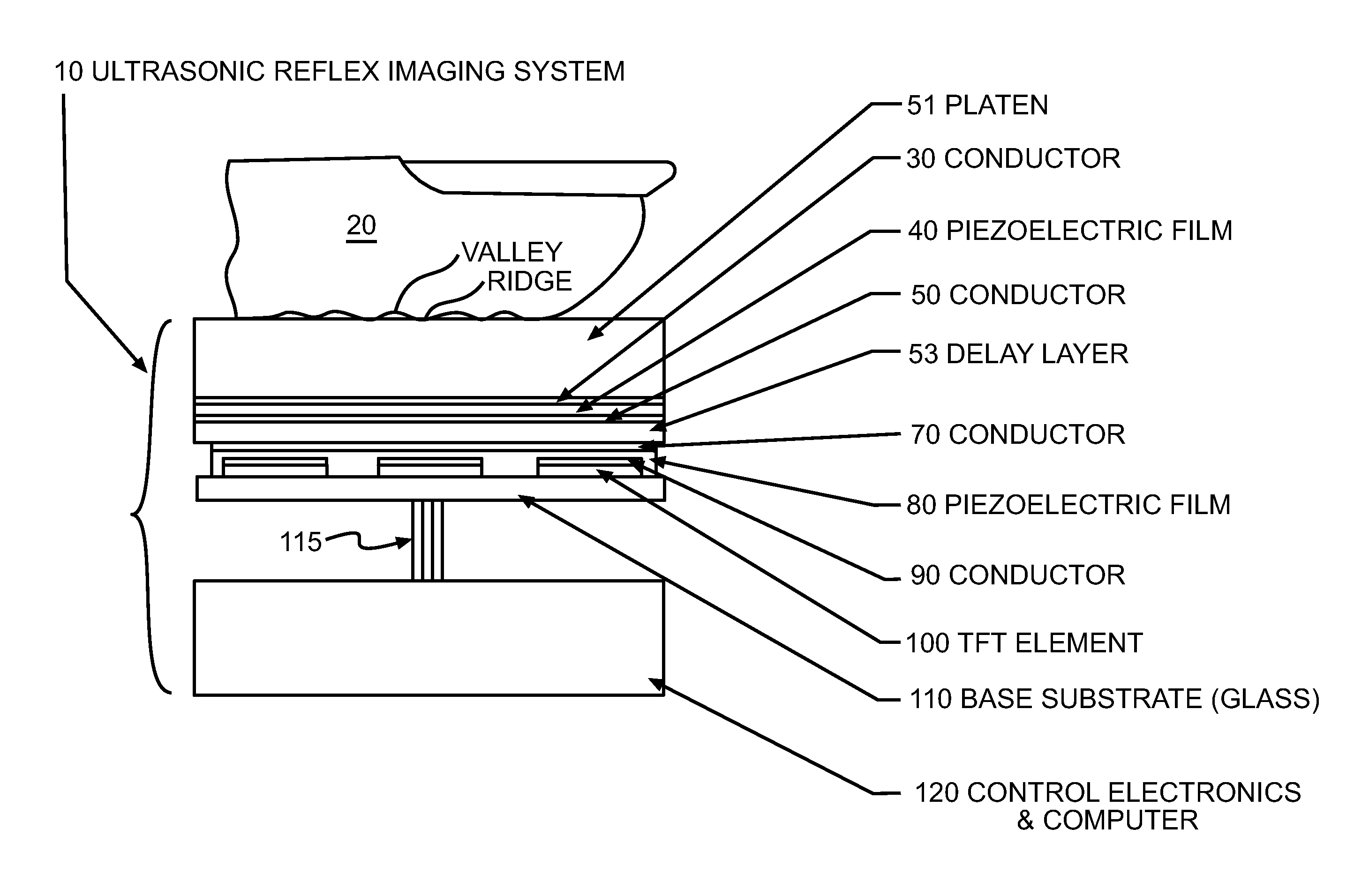
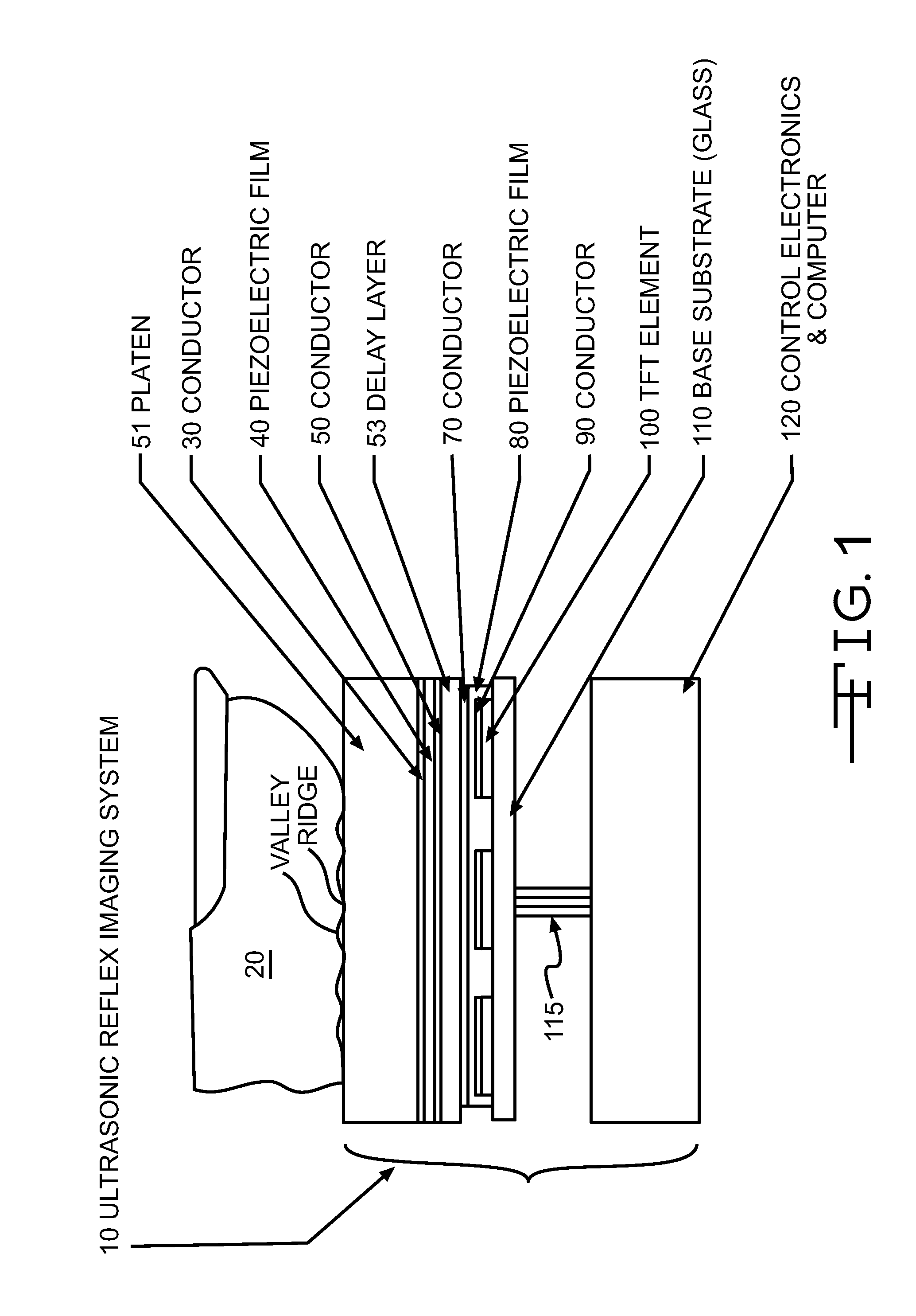
[0015]FIG. 1 depicts a scanner 10 according to the invention. The scanner 10 may be used to obtain biometric information, such as a fingerprint from a finger 20. Such information may be used to authenticate the identity of an individual. The device depicted in FIG. 1 utilizes an array of detecting elements in a two-dimensional layout, which is sometimes referred to as an “area array”. The scanner 10 may be used to capture a fingerprint image representing the friction ridge surface of a finger 20. The scanner 10 may be implemented in a manner that gives it a competitive advantage over other currently available electronic fingerprinting systems. For example, the invention may be deployed in a form that is capable of imaging a small (¼″×¼″) area, but that design may be scalable to afford imaging of a large area, which could be several meters in length and several meters in width. An imaging area that is 3.0″×3.2″ might be preferred so that four fingers can be imaged simultaneously. Als...


PUM


Abstract

A biometric scanner is described and claimed. The scanner has a platen, an ultrasonic plane wave generator, an ultrasonic detector, and a delay layer residing between the generator and the detector.

Description

CROSS-REFERENCE TO RELATED APPLICATION[0001]This application claims the benefit of priority to U.S. provisional patent application Ser. No. 61 / 311,667, filed on Mar. 8, 2010.FIELD OF THE INVENTION[0002]The present invention relates to an ultrasonic reflex (i.e. reflected) imaging system that is constructed such that it employs a plane wave ultrasound pulse generator, and uses a separate detector array, and there is a layer of material which delays movement of the energy. The delay layer resides in the path of the ultrasound energy.BACKGROUND OF THE INVENTION[0003]Since the 1800's fingerprint information has been collected from human fingers and hands by means of ink and paper. For the purposes of this document, the term fingerprint is used to mean the skin surface friction ridge detail of a single fingerprint, partial fingerprint or any portion of the skin surface friction ridge of up to and including the entire hand. In recent years various electronic fingerprint scanning systems h...

Claims


Application Information

Patent Timeline
IPC IPC(8): G06K7/00
CPCG06K9/0002G06V40/1306
Inventor SCHNEIDER, JOHN K.KITCHENS, JACK C.
Owner QUALCOMM INC
Why Eureka
Try Eureka