Gas turbine blade, manufacturing method therefor, and gas turbine using turbine blade

Inactive Publication Date: 2011-09-08
MITSUBISHI HEAVY IND LTD
View PDF6 Cites 7 Cited by
  • Summary
  • Abstract
  • Description
  • Claims
  • Application Information

AI Technical Summary

Benefits of technology

[0008]The present invention has been conceived in light of the above-described circumstances, and an object thereof is to provide gas turbine blades that are capable of simplifying the formation of cooling channels provided inside the turbine blades while sim

Problems solved by technology

However, with the structure in Japanese Unexamined Patent Application, Publication No. 2007-211618, because the hollow portion is formed as a single space, the effective cross-sectional area of the turbine blade ends up being reduced at this portion, thus causing a loss of turbine blade strength and rigidity; in the worst case, breakage (creep rupture, etc.) may be caused, and there has been a lack of reliability.
If the hollow portio

Method used


Image

  • Gas turbine blade, manufacturing method therefor, and gas turbine using turbine blade
  • Gas turbine blade, manufacturing method therefor, and gas turbine using turbine blade
  • Gas turbine blade, manufacturing method therefor, and gas turbine using turbine blade

Examples


Example

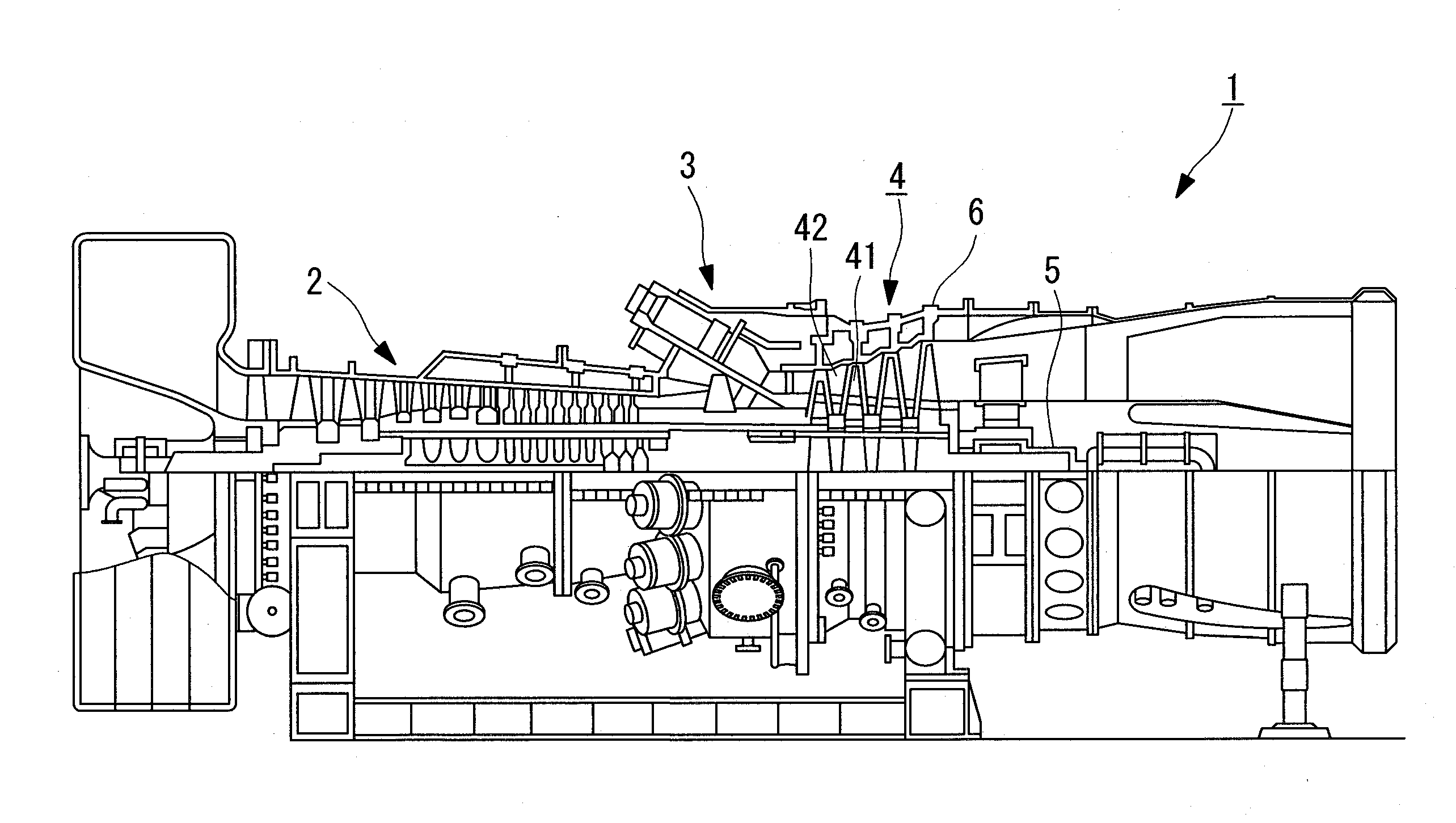
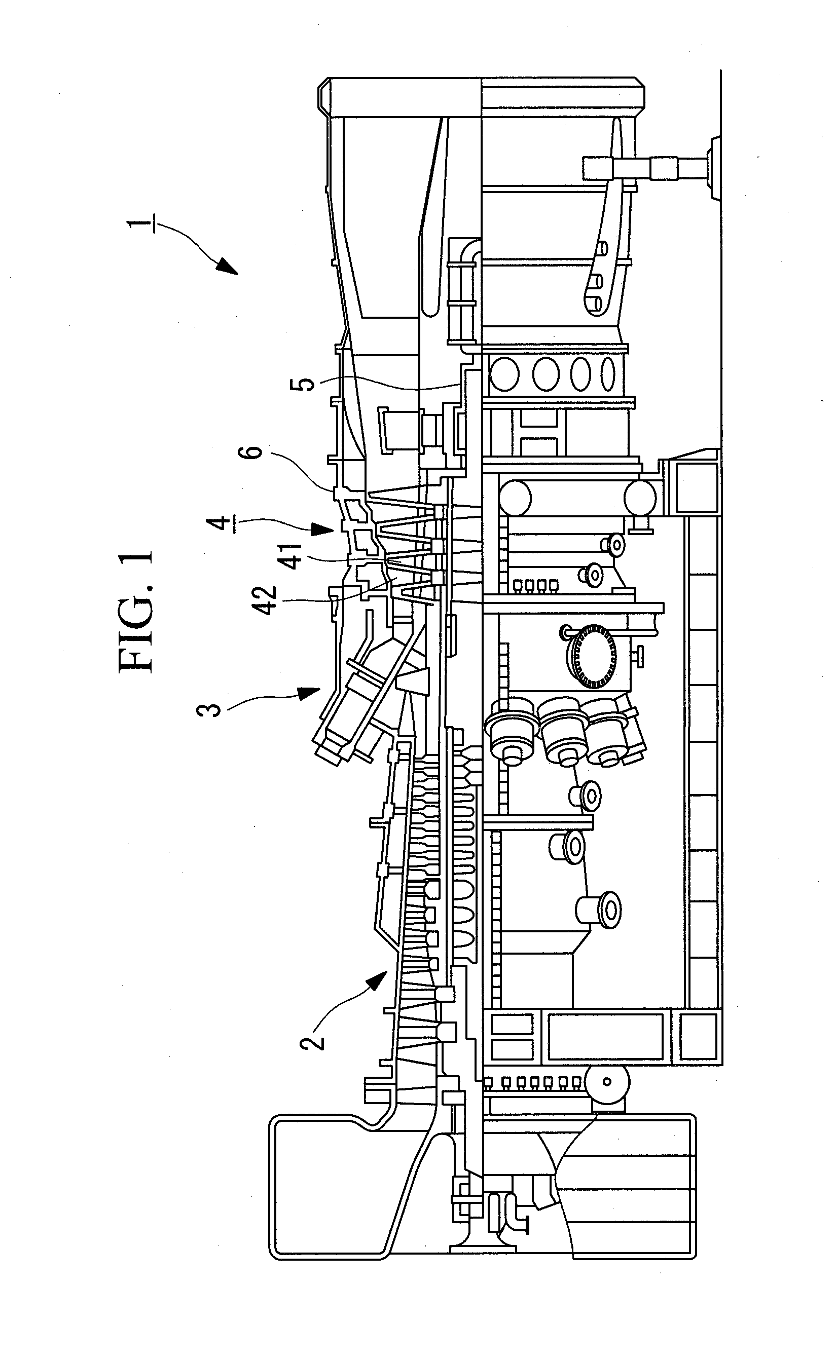
[0030]FIGS. 1 to 6 show a first embodiment of the present invention. FIG. 1 is an overall configuration diagram showing an example of a gas turbine to which turbine blades according to the present invention are applied. The gas turbine 1 is provided with a compressor 2, a combustor 3, and a turbine 4. The compressor 2 compresses the air taken in from an air-intake port to generate compressed air. The combustor 3 generates high-temperature, high-pressure combustion gas by spraying fuel into the compressed air. The turbine 4 generates a driving force by converting the thermal energy of the combustion gas into the rotational energy of a rotor 5. Then, the driving fore is transmitted to a generator (not shown) or the like connected to the rotor 5. The turbine 4 is disposed inside a turbine housing 6 which is provided so as to connect with the combustor 3.

[0031]The turbine 4 includes several stages of turbine blades 41 that are disposed in the rotor 5 so as to integrally rotate therewith...

Example

Second Embodiment

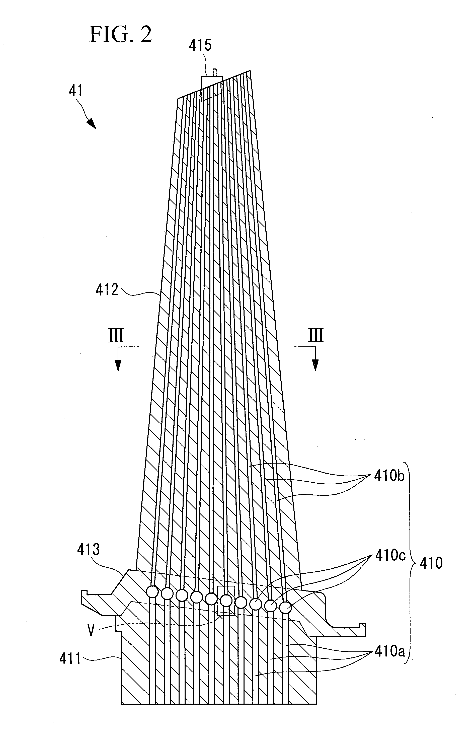
[0048]Next, a second embodiment of the present invention will be described with reference to FIG. 8. Except for the point that the positions in the longitudinal direction differ for the plurality of the communicating hollow portions 410c that constitute the cooling channels 410, turbine blades 51 illustrated in this second embodiment are similar to the turbine blades 41 of the first embodiment shown in FIG. 2.

[0049]Here, the communicating hollow portions 410c are disposed, for example, in a staggered manner by varying the heights thereof in the vertical direction, so that the heights of the communicating hollow portions 410c that are adjacent to each other among the plurality of the communicating hollow portions 410c differ. Even if the heights are altered in this way, it is desirable that all of the communicating hollow portions 410c be formed so as to be positioned inside the platform portions 413.

[0050]With this configuration, the communicating hollow portions 41...


PUM

PropertyMeasurementUnit
Speedaaaaaaaaaa
Heightaaaaaaaaaa
Strengthaaaaaaaaaa

Abstract

Provided are gas turbine blades in which it is possible to simplify the formation of cooling channels provided inside the turbine blades while simultaneously avoiding loss of turbine blade strength and rigidity due to forming of the cooling channels. In a gas turbine blade, cooling channels provided in the interior thereof include a plurality of straight channel-like base-side elongated holes that extend in a longitudinal direction at a base side of the turbine blade, a plurality of straight channel-like tip-side elongated holes that extend in a longitudinal direction at a tip side of the turbine blade, and a plurality of communicating hollow portions that are interposed at connection portions between the two types of elongated holes to individually allow the two types of elongated holes to communicate with each other and that have larger cross-sectional areas than the channel cross-sectional areas of both elongated holes. In addition, the communicating hollow portions are formed so as to match the position of a platform portion of the turbine blade.

Description

BACKGROUND OF THE INVENTION[0001]1. Field of the Invention[0002]The present invention relates to gas turbine blades used in thermal power generation and so forth and relates, more specifically, to gas turbine blades in which cooling channels formed inside the turbine blades are improved, to a manufacturing method therefor, and to a gas turbine using the turbine blades.[0003]This application is based on Japanese Patent Application No. 2010-046687, the content of which is incorporated herein by reference.[0004]2. Description of Related Art[0005]In a gas turbine, because high-temperature working fluid flows in the area surrounding turbine blades, in general, cooling channels are formed inside the turbine blades in the longitudinal direction of the turbine blades, and cooling of the turbine blades is performed by streaming cooling air through the cooling channels. Part of the air compressed by a turbine compressor is extracted and fed into the cooling channels as the cooling air, and th...

Claims


Application Information

Patent Timeline
IPC IPC(8): F01D5/18B23P15/02
CPCF01D5/187F05D2250/70Y10T29/49341F01D5/225F05D2230/11F01D5/18F02C7/00B23H9/10F02C7/18
Inventor HADA, SATOSHIIMADA, TAKAHIKOSHINTANI, TOMOFUMIOOE, KATSUTOSHIHIRATA, NORIFUMIASANO, HIROSHI
Owner MITSUBISHI HEAVY IND LTD
Why Eureka
Try Eureka