
Apparatus for Movable and Weight-Compensating Suspension of a Focusing Objective of a Laser System

a laser system and focussing objective technology, applied in laser surgery, medical science, surgery, etc., can solve the problem of putting considerable weight on the scale, and achieve the effect of reliable and precise functioning

Active Publication Date: 2011-09-08
ALCON INC
View PDF5 Cites 33 Cited by
  • Summary
  • Abstract
  • Description
  • Claims
  • Application Information

AI Technical Summary

Benefits of technology

[0007]a force generation device to generate a counterforce component which counteracts the weight of the focussing objective,
[0021]For example, the guidance device can include a linear bearing and a slide which is guided in it. The slide can be fixed on the focussing objective. The linear bearing can also include at least one guidance groove. The slide can also include at least one guidance projection, which is set up to work with the guidance groove in such a way that movement of the slide in a horizontal direction is avoided. In this way, guidance of the focussing objective in a vertical direction is made possible, the optical axis of the focussing objective being able to maintain its alignment and position in the case of a compensatory movement of it relative to an initial position. For this purpose, the guidance groove can be formed with an undercut, into which the guidance projection engages.

Problems solved by technology

Focussing objectives in laser systems are often multi-lens systems, which can put considerable weight on the scales.

Method used


Image

  • Apparatus for Movable and Weight-Compensating Suspension of a Focusing Objective of a Laser System
  • Apparatus for Movable and Weight-Compensating Suspension of a Focusing Objective of a Laser System

Examples


Embodiment Construction

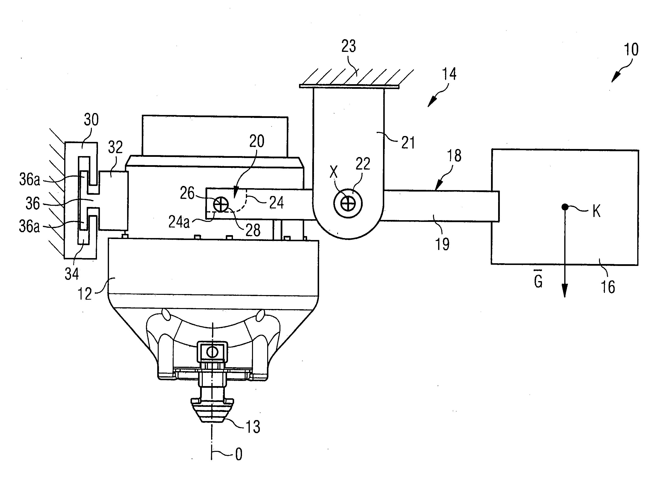
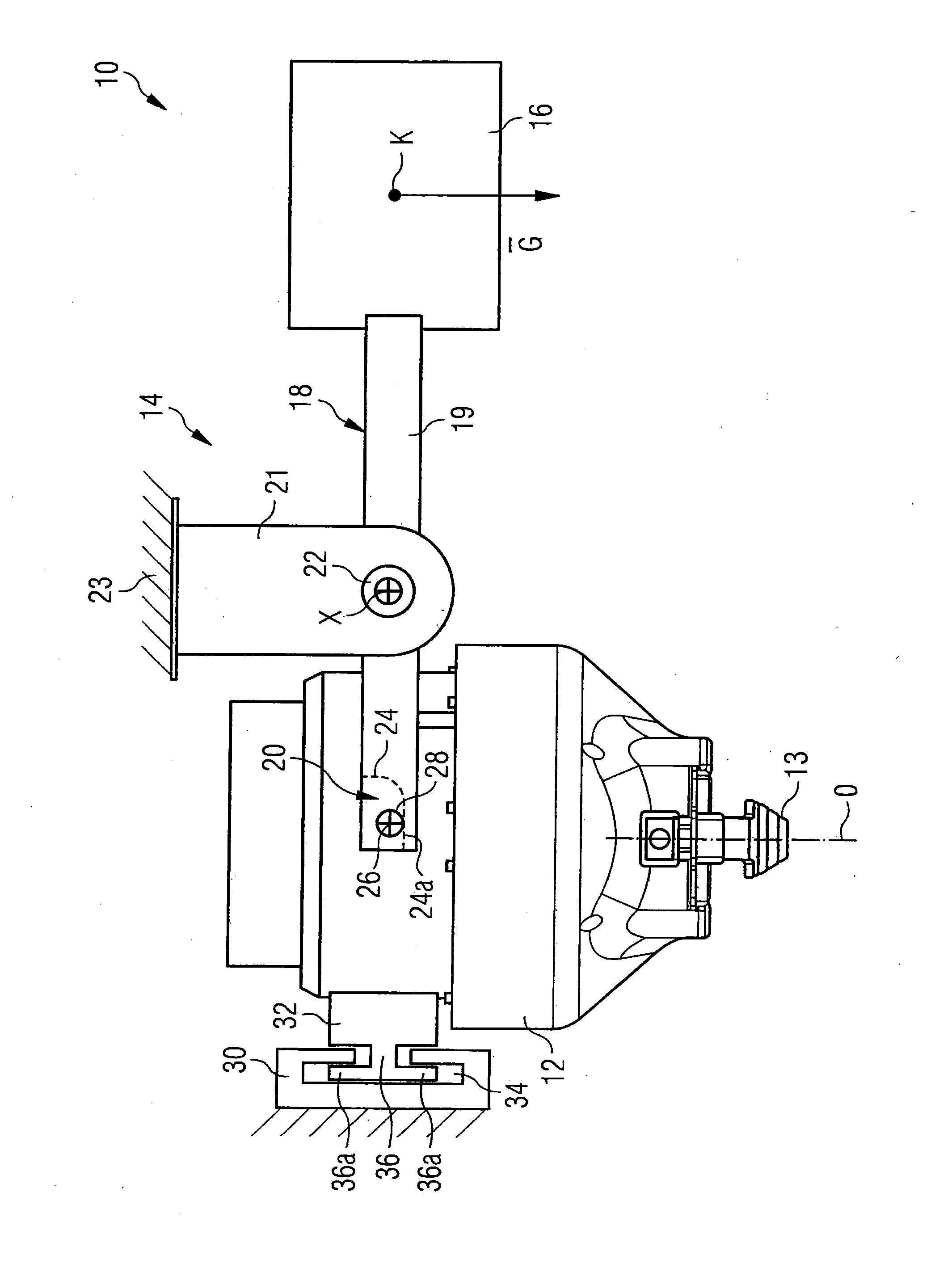
[0029]Of the laser system, which as whole is marked with 10, only the “output stage” is shown in the drawing, i.e. essentially only a focussing objective 12 with a patient adapter 13 arranged on the radiation exit side of it. The focussing objective 12 is weight-compensated and movably suspended by a suspension apparatus 14. If “weight compensation” is mentioned here, it means compensation for at least a pre-dominant part of the weight of the objective 12. A particularly small residual part of the objective weight can remain without compensation, e.g. of the order of magnitude of a few newtons of weight. The focussing objective 12 focusses, in a way which is not shown in more detail, an afocal beam of rays of the laser radiation pro-vided by the laser system 10 onto a focus location within the eye tissue to be cut. The laser radiation which is used has, for example, pulse durations in the femtosecond range, and a wavelength in the low infrared range (e.g. between approx. 1000 and ap...


PUM


Abstract

An apparatus for movable weight-compensating suspension of a focussing objective of a laser system comprises a force generation device to generate a counterforce component G which counteracts the weight of the focussing objective, a transmission device which transmits the counterforce component G onto the focussing objective and permits upward / downward compensatory movement of the focussing objective, in such a way that in the case of an upward / downward compensatory movement of the focussing objective, an optical axis (O) of the focussing objective maintains at least its orientation in space, and preferably its position in space.

Description

FIELD OF THE INVENTION[0001]The invention concerns movable weight-compensating suspension of a focussing objective of a laser system. The laser system preferably provides pulsed laser radiation, which is focussed by means of the focussing objective onto a desired location where the radiation is to act.BACKGROUND OF THE INVENTION[0002]Movable weight-compensating suspension of the focussing objective is desired, not exclusively but above all, where treatment of living tissue is involved, and there is direct contact between the tissue and the laser system. Such direct contact is often produced, for example, in the case of operations on the human eye using laser surgery, when incisions in the cornea or other parts of the eye are to be made using ultra-short pulses of laser radiation. In this case, direct contact is intended to ensure precise positioning of the eye to be treated relative to the laser system in the direction of propagation of the radiation. Usually, a suitable interface u...

Claims


Application Information

Patent Timeline
IPC IPC(8): A61F9/008G02B7/02
CPCG02B7/02A61F9/008A61F9/009A61F9/00825
Inventor ROBL, GERHARD
Owner ALCON INC
Learn More