Video display system and display control method
a video display system and display control technology, applied in the field of video display systems, can solve the problem of careless opening of unsuitable data, and achieve the effect of improving the security of the video display system and displaying only presentation video images
- Summary
- Abstract
- Description
- Claims
- Application Information
AI Technical Summary
Benefits of technology
Problems solved by technology
Method used
Image
Examples
embodiment 1
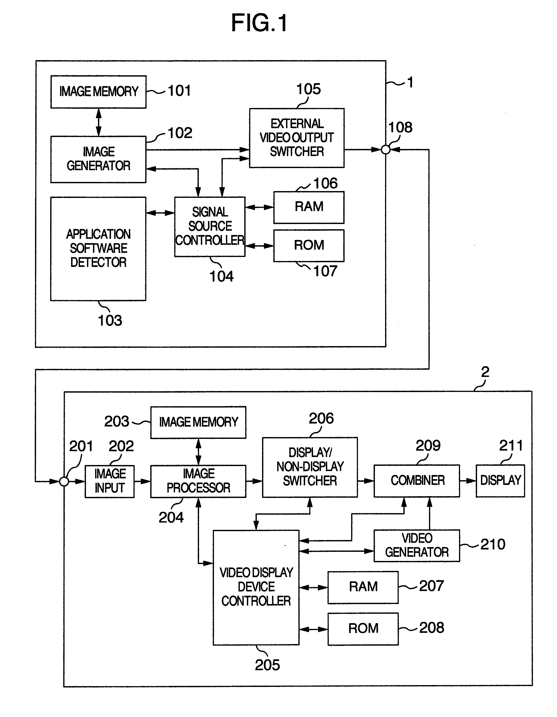
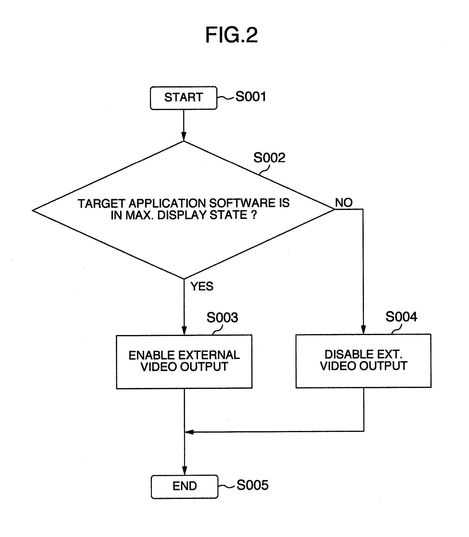
[0035]An explanation will now be given of the first embodiment that applies this invention to a signal source, with reference to FIG. 1, FIG. 2, FIGS. 3A-3C and FIG. 4. FIG. 1 is a block diagram showing one example of a configuration of the signal source and a video display device used in the embodiment of this invention. More precisely, the signal source may be a PC which is operatively associated with the video display device, such as LCD projector, for displaying video images on a large-size screen by use of an application software program.
[0036]In FIG. 1, reference numeral “1” is used to designate the signal source; numeral 101 indicates an image memory; numeral 102 denotes an image generation unit; 103 is an application software detection unit; 104, a signal source control unit; 105, an external video output switching unit. The image memory 101, image generator unit 102, application software detector unit 103 and external video output switcher unit 105 are controlled by the sig...
embodiment 2
[0050]The second embodiment incorporating the principles of this invention will be described using FIG. 1, FIGS. 3A-3C and FIG. 5.
[0051]FIG. 1 is a block diagram showing an exemplary configuration of the signal source and video display device used in the embodiment of this invention. Reference numeral 202 denotes an image input unit; numeral 203 indicates an image memory; 204 is an image processing unit; 205, a video display device control unit; 206, a display / non-display switching unit. The image memory 203, image processor unit 204, display / nondisplay switcher 206 are controlled by the video display device controller 205, for example. The image memory 203 and image processor 204 is constituted from a semiconductor memory device(s), for example, in which is stored the information concerning the image data acquired at the image input unit 202.
[0052]In this embodiment, the video display device 2 operates to inspect those images held in the image memory 203 and image processor 204 to ...
embodiment 3
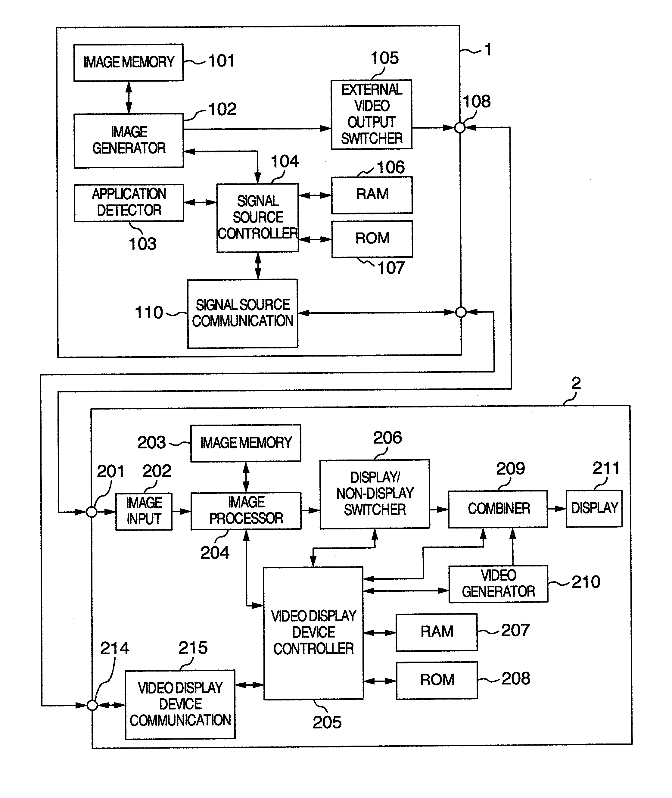
[0058]An explanation will be given of the third embodiment of this invention with reference to FIGS. 6 and 7, which embodiment applies the concept of the invention to a video display system having a signal source and a video display device that are connected together by a video cable and a communication cable. FIG. 6 is a block diagram showing one example of a connection arrangement between the signal source and video display device in accordance with the third embodiment of this invention. Numeral 110 designates a signal source communication unit whereas numeral 215 indicates a video display device communication unit.
[0059]In the system shown herein, the image memory 101, image generator 102, application software detector 103, external video output switcher 105 and signal source communication unit 110 are controlled by the signal source control unit 104, for example. The image memory 203, image processor 204, display / nondisplay switcher 206 and video display device communication un...
PUM
 Abstract
Description
Claims
Application Information
 - R&D
- Intellectual Property
- Life Sciences
- Materials
- Tech Scout
- Unparalleled Data Quality
- Higher Quality Content
- 60% Fewer Hallucinations
Browse by: Latest US Patents, China's latest patents, Technical Efficacy Thesaurus, Application Domain, Technology Topic, Popular Technical Reports.
© 2025 PatSnap. All rights reserved.Legal|Privacy policy|Modern Slavery Act Transparency Statement|Sitemap|About US| Contact US: help@patsnap.com


