
Solar cell having a graded buffer layer

a buffer layer and solar cell technology, applied in the field of solar cells having a graded buffer layer, can solve the problem of poor epitaxy quality of ingaas cells with lower bandgap energy

Inactive Publication Date: 2011-09-15
EPISTAR CORP
View PDF6 Cites 32 Cited by
  • Summary
  • Abstract
  • Description
  • Claims
  • Application Information

AI Technical Summary

Benefits of technology

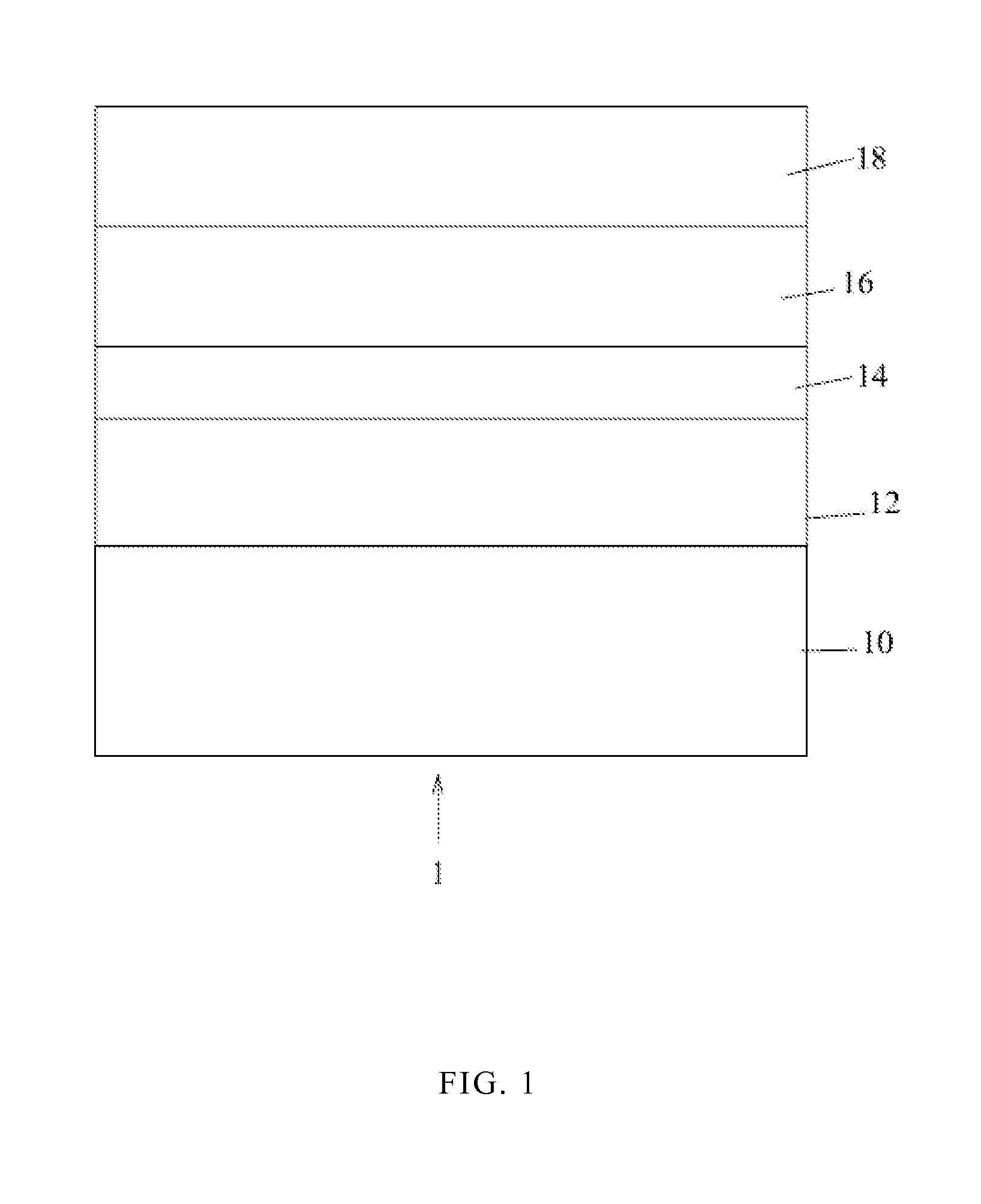
The present patent describes a new type of solar cell that has multiple layers. The bottom layer is made up of a supporter and a graded buffer layer. The middle layer is made up of a graded buffer layer and a middle cell. The top layer is made up of a graded buffer layer and a top cell. This design helps to improve the performance of the solar cell.

Problems solved by technology

Despite IMM structure improves the energy conversion efficiency, the epitaxy quality for the InGaAs cell with lower bandgap energy is not good enough.

Method used


Image

  • Solar cell having a graded buffer layer
  • Solar cell having a graded buffer layer
  • Solar cell having a graded buffer layer

Examples


Embodiment Construction

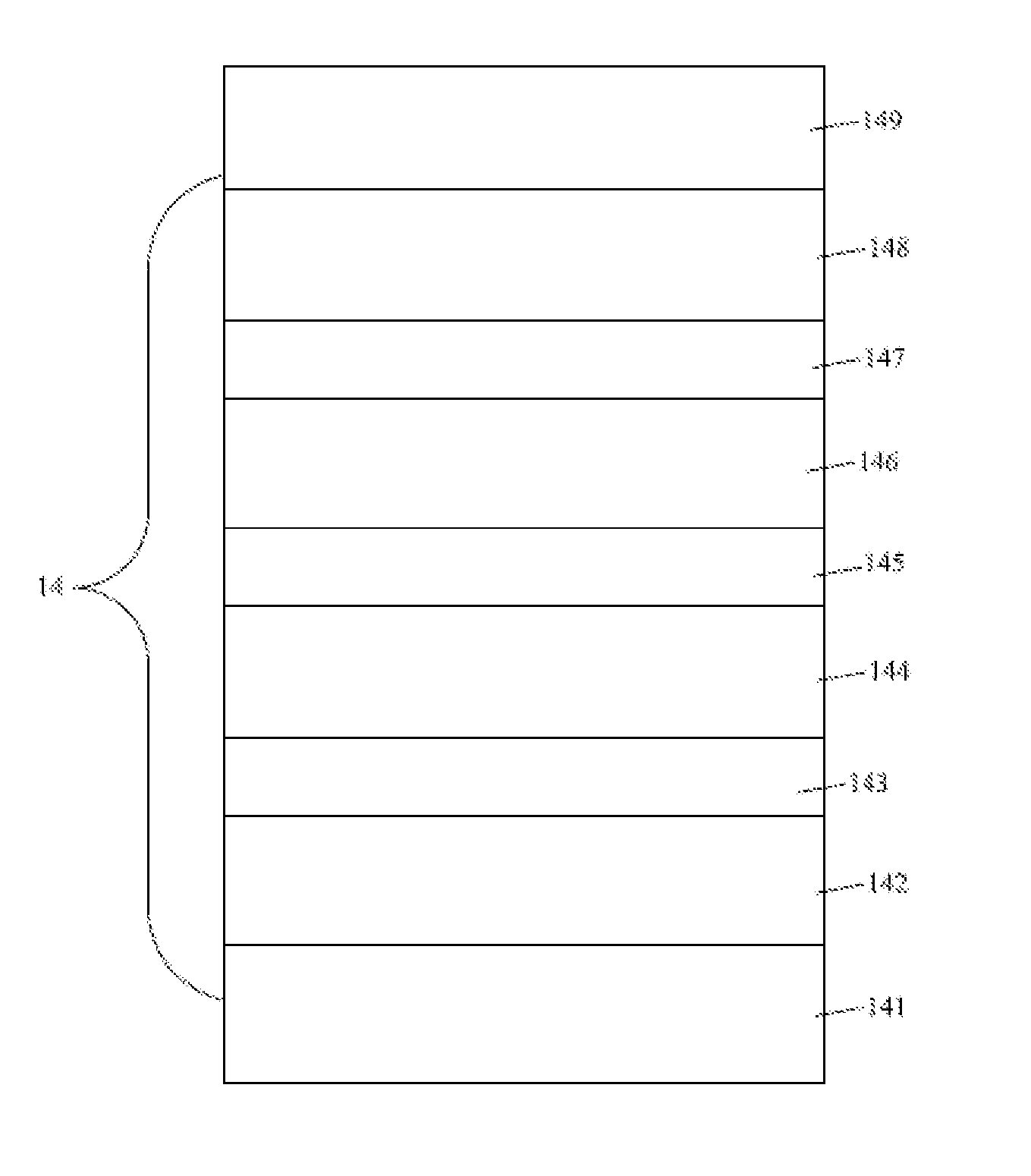
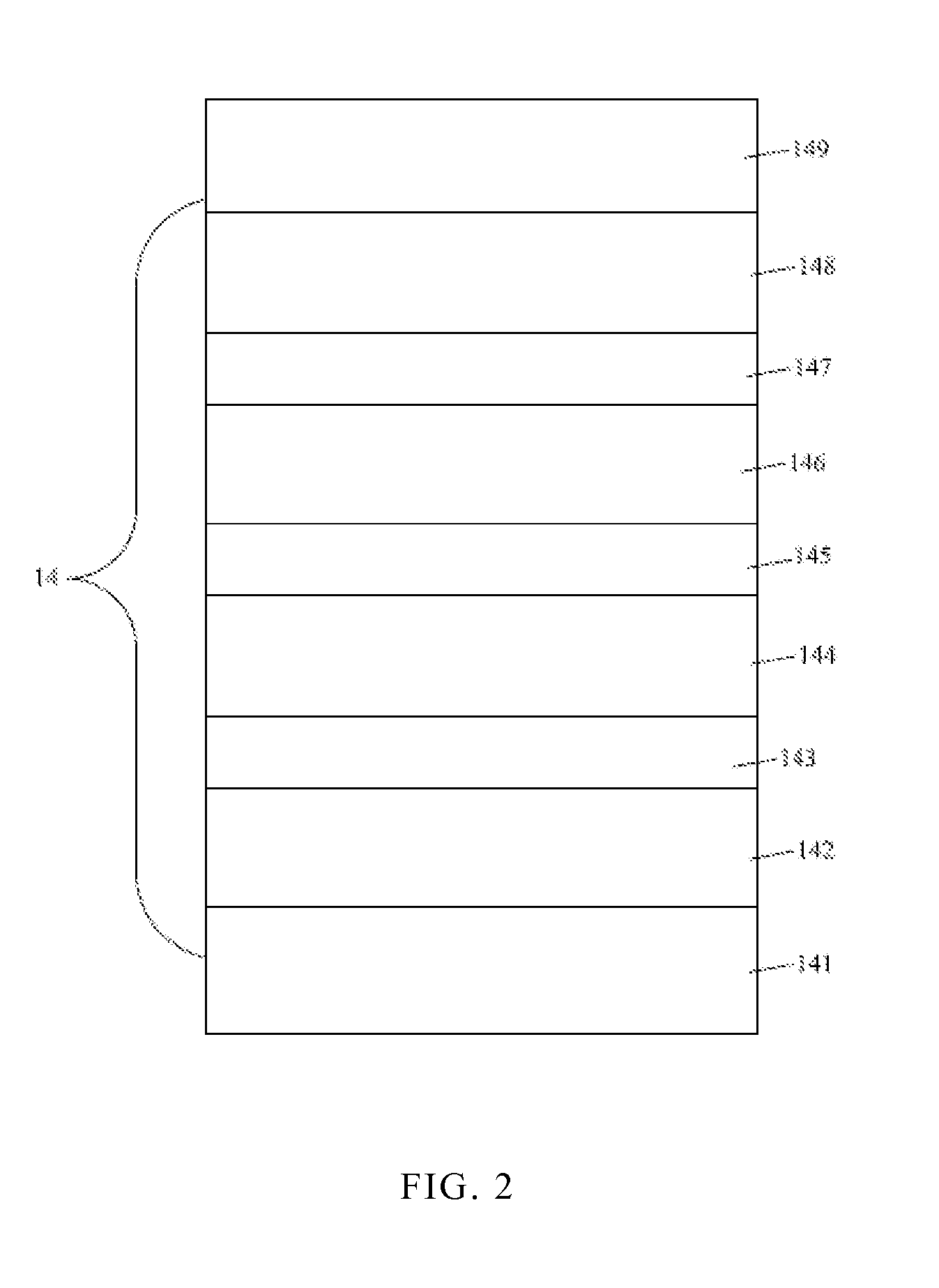
[0011]In FIG. 1, an IMM solar cell 1 comprises a supporter 10; a bottom cell 12 comprising a bottom p-n junction on the supporter 10; a graded buffer layer 14 on the bottom cell 12; a middle cell 16 comprising a middle p-n junction on the graded buffer layer 14; and a top cell 18 comprising a top p-n junction on the middle cell 16. A bandgap energy of the top cell 18 (or the top p-n junction) is greater than those of the middle cell 16 (or the middle p-n junction) and the bottom cell 12 (or the bottom p-n junction). The material of the top cell 18 comprises InGaP, InGaAs, AlGaAs, or AlGaInP. A bandgap energy of the middle cell 16 or the middle p-n junction is greater than the bottom cell 12 or the bottom p-n junction. The material of the middle cell comprises GaAs, GaInP, InGaAs, GaAsSb, or InGaAsN. The material of the bottom cell 12 comprises Ge, GaAs, or InGaAs. The top cell 18, middle cell 16, and the bottom cell 12 can convert light within different spectrum ranges to electrical...


PUM


Abstract

An IMM solar cell includes a substrate, a bottom cell on the substrate; a graded buffer layer on the bottom cell; a middle cell on the graded buffer layer; a top cell on the middle cell.

Description

RELATED APPLICATION DATA[0001]This application claims the right of priority based on CN application Ser. No. 201010142921.3 filed on Mar. 19, 2010, the contents of which are incorporated herein by reference in their entirety.BACKGROUND[0002]1. Technical Field[0003]The application relates to a solar cell having a graded buffer layer and the manufacturing method thereof.[0004]2. Description of the Related Art[0005]Light-emitting diodes (LED), solar cells, or photo-diodes are all optoelectronic devices. Recently, researchers have been actively developing the technologies related to alternative energy and renewable energy due to the shortage of fossil fuel and the great emphasis on the environment conservation. The solar cell is one of the most important options because the solar cell can directly transmit solar energy into electrical energy without producing the hazardous material, such as carbon dioxide or nitride material, that poisons the environment.[0006]The inverted metamorphic m...

Claims


Application Information

Patent Timeline
Patent Type & Authority Applications(United States)
IPC IPC(8): H01L31/06
CPCH01L31/03046H01L31/06875H01L31/0725Y02E10/544H01L31/078H01L31/1844H01L31/1852H01L31/0735
Inventor LEE, RONG-RENLIN, SHIUAN-LEHLEE, SHIN-CHANG
Owner EPISTAR CORP
Learn More