Support system for solar panels

a solar panel and support system technology, applied in the direction of solar thermal energy generation, solar heating energy, heat collector mounting/support, etc., can solve the problems of unstable panel mounting, poor structural quality, and difficult installation of solar panels on the support structure, so as to facilitate both temporary and permanent placement of wires, facilitate protection of long cable runs, and facilitate the effect of flexibility

Inactive Publication Date: 2011-09-15
NORTHERN STATES METALS
View PDF74 Cites 44 Cited by
  • Summary
  • Abstract
  • Description
  • Claims
  • Application Information

AI Technical Summary

Benefits of technology

[0019]It is another object of the present invention to provide a support and installation system for solar panels in which the panels and installation site are less likely to be damaged during installation.
[0057]It is the overall goal of the present invention to provide a comprehensive panel mounting system that facilitates rapid, secure installation, including deployment of the panel support structure, placement of the panels on that support structure, and wiring of the panels for activation.

Problems solved by technology

Typically, these support systems are costly, labor intensive to install, heavy, structurally inferior, and mechanically complicated.
Placing the solar panels on the support structure can be very difficult, as can wiring of the solar panels for array activation.
Further, some large solar panels tend to sag and flex thereby rendering the panel mounting unstable.
Unstable panel arrangements also jeopardize the integrity of the wiring arrangement, which is necessary for the photovoltaic panels to be useful.
This installation process is usually inaccurate, and time-consuming, even with expensive, skilled installers.
Notably, existing support systems require meticulous on-site assembly of multiple parts, performed by expensive, dedicated, field labor.
Assembly is often performed in unfavorable working conditions, i.e. in harsh weather and over-difficult terrain, without the benefit of quality control safeguards and precision tooling.
Misalignment of the overall support assembly often occurs.
This can jeopardize the supported solar panels 12, or other supported devices.
Further, wiring of the solar panels, once secured, is also problematic in conventional systems.
It is difficult, however, to precisely space the panels on-site using existing support structures without advanced (and expensive) technical assistance.
Unfortunately, the operation of drilling the holes on-site requires skilled workers, and even with skilled installation, might still result in misalignment of the support structure and / or the solar panels supported by that structure.
Misalignment difficulties are exacerbated by the flexing of the panels 12, and the sagging permitted by the flexibility of the panels.
The sagging of the panels can cause the panels to work out of their holders, whether they would be holding clips or part of the overall structure of the upper support rail.
Improper installation, which occurs frequently in conventional systems, can lead to dislocation of the panels due to sagging or atmospheric conditions.
A wide variety of different mounting positions and array arrangements also exacerbate the stability problems caused by panel sagging or deflection.
Further, certain mounting positions will make the panels more vulnerable to atmospheric disruptions, such as those created by wind and precipitation.
All of these variables further complicate electrical connections in the panel array.
This support arrangement is not always available.
Even a stable flat roof presents problems for the mounting of an array of solar panels.
In particular, the panels cannot be mounted in the same manner that is provided in FIGS. 1 through 4B of the present application.
Flat roofs, while serving as preferred surfaces for solar panels, are also particularly susceptible to damage since even slight indentations caused by the stresses inherent to installing a heavy panel array 10, may cause water to pool on parts of the roof, thereby compromising the integrity of the roof.
Otherwise, the increased activity of installation becomes detrimental to the flat roof structure.
Unfortunately, wiring arrangements tend to change with the types of panels and panel configurations being deployed.
This causes a lack of predictability, which keeps installers on the roof structures for extended periods of time, thereby applying increased stress to flat roofs.
At present, none of the conventional art offers these capabilities.

Method used


Image

  • Support system for solar panels
  • Support system for solar panels
  • Support system for solar panels

Examples


Embodiment Construction

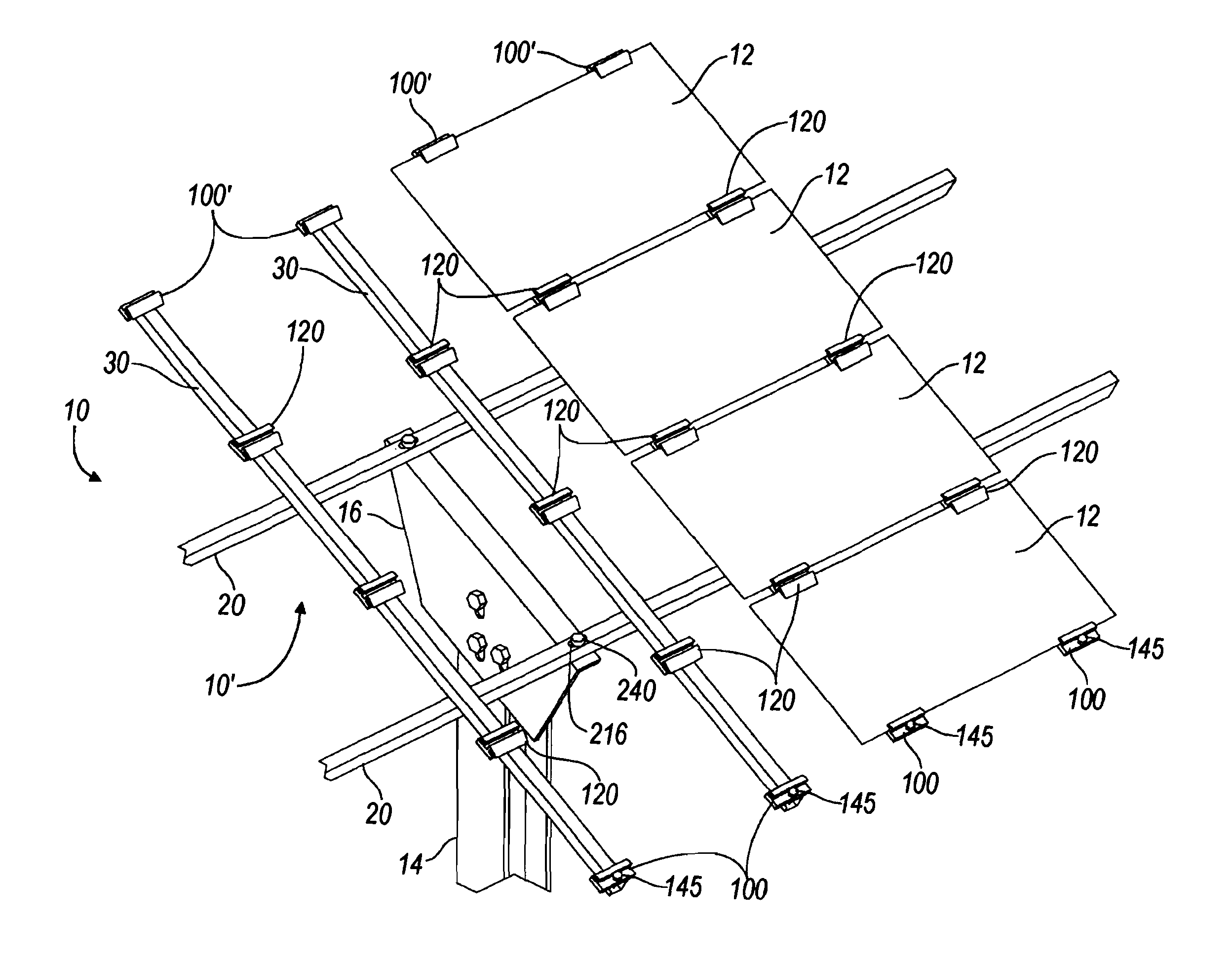
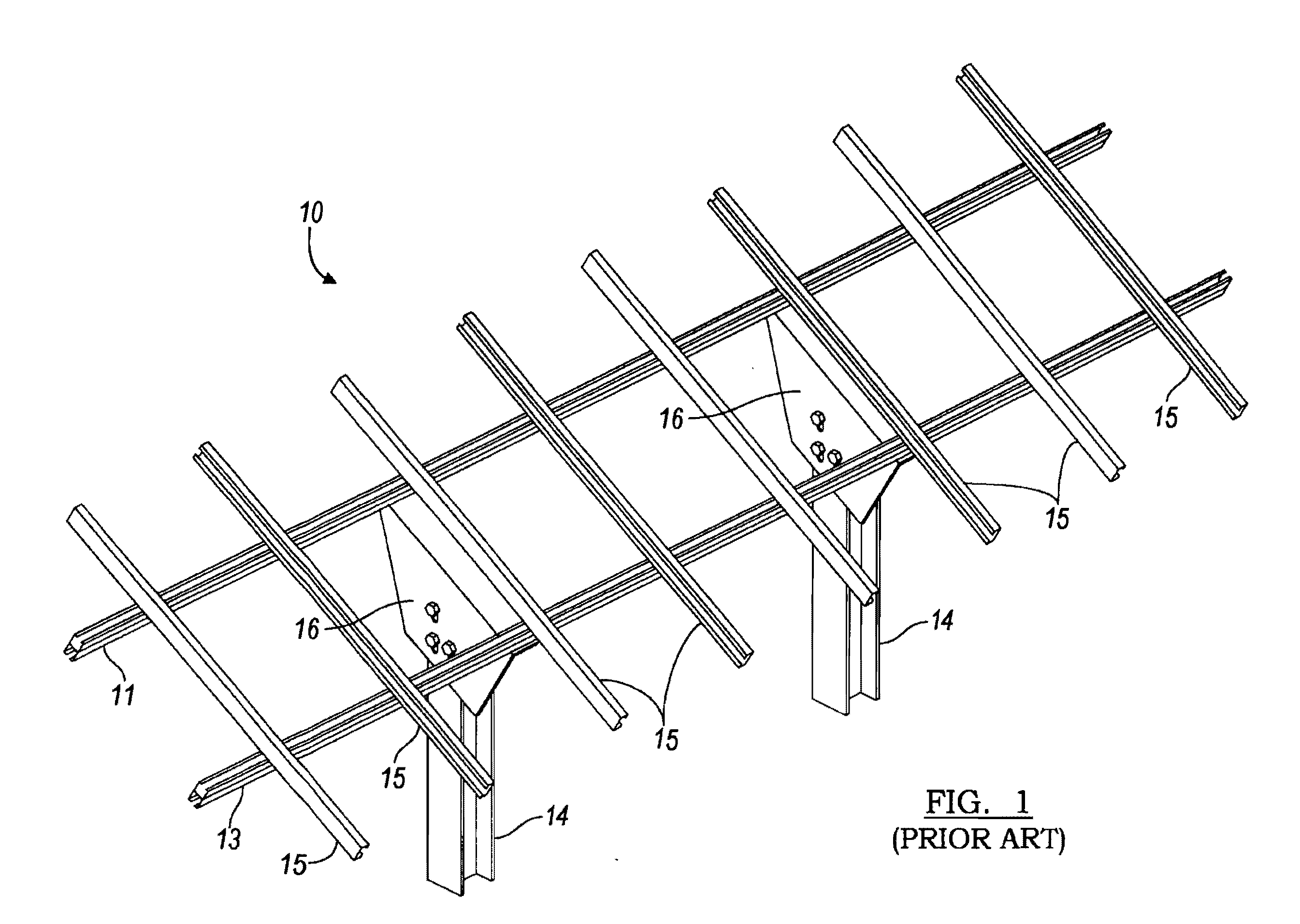
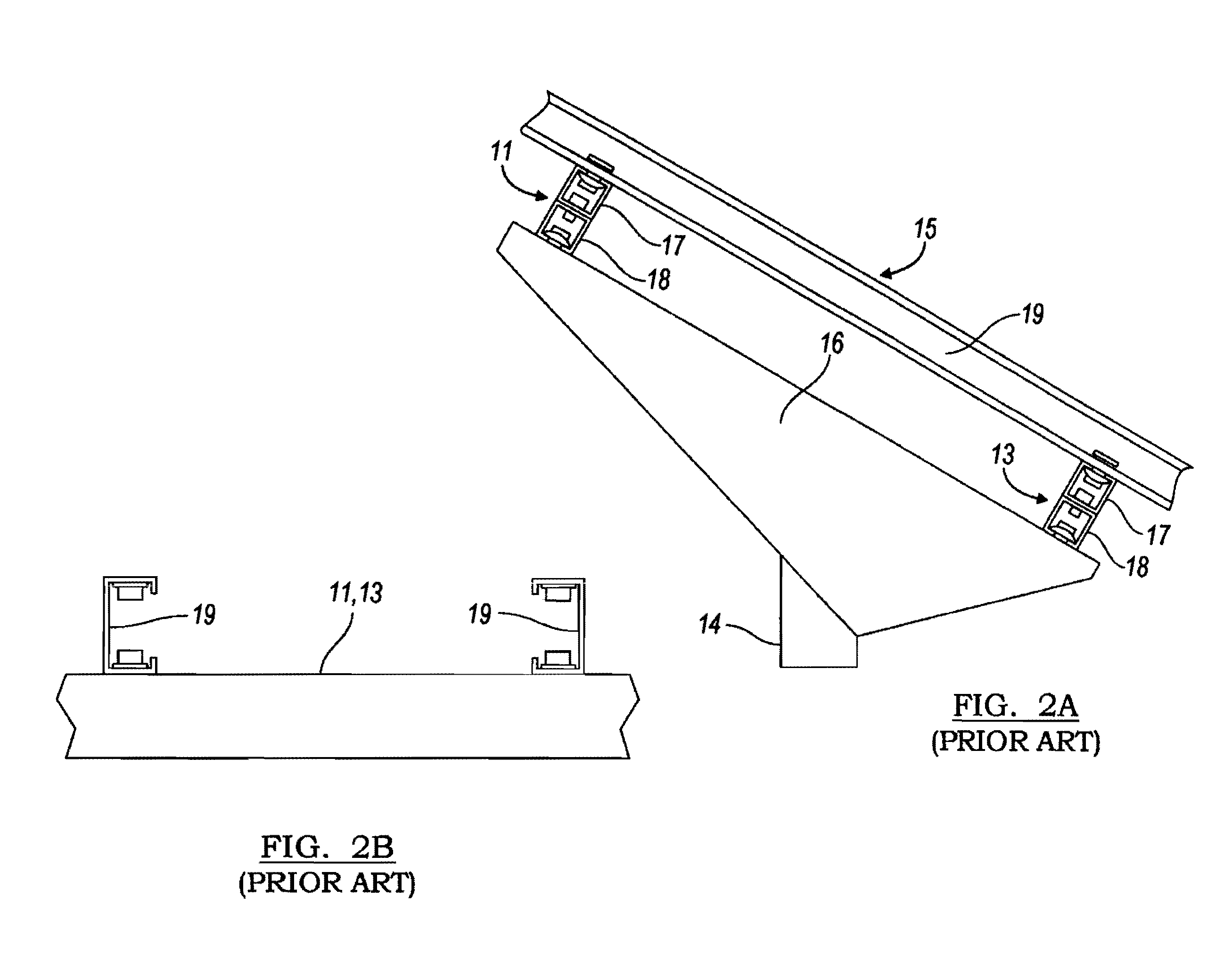
[0095]The present invention is used in the conventional environment depicted in FIGS. 1-2B, and is an improvement upon the previously disclosed inventions depicted in FIGS. 3-7. The previously disclosed inventions by the same inventors are found in U.S. patent application Ser. No. 12 / 383,240 (filed Mar. 20, 2009); U.S. patent Ser. No. 12 / 567,908 (filed Sep. 23, 2009); and, Ser. No. 12 / 686,598 (filed Jan. 13, 2010). All of these patent applications describe the inventions. The present patent application relies on all three for priority, and incorporates all by reference for purposes of providing a more complete background for the instant invention.

[0096]FIGS. 3-7 are relied upon as disclosing the bi-directional panel support matrix environment in which the improvements of the present application operate. Only a summary of the structures depicted in FIGS. 3-7 is provided herein, sufficient for an understanding of the background of the present invention. Full, detailed descriptions of ...


PUM

PropertyMeasurementUnit
angleaaaaaaaaaa
angleaaaaaaaaaa
structureaaaaaaaaaa

Abstract

A panel support and wiring system is used as part of a bi-directional solar panel support matrix having lower support joists and upper panel rails. Both the panel clip and wiring arrangements are configured to facilitate rapid deployment and installation of the entire solar panel system, including supports and interfaces with the underlying substrate. A standardized wiring system is one of the factors facilitating rapid installation.

Description

PRIORITY INFORMATION[0001]The present application claims priority as a continuation-in-part application from U.S. patent application Ser. No. 12 / 686,598, filed Jan. 13, 2010, which is a continuation-in-part application from U.S. patent application Ser. No. 12 / 567,908 filed on Sep. 28, 2009, which is a continuation-in-part application from parent U.S. patent application Ser. No. 12 / 383,240 filed on Mar. 20, 2009, U.S. Provisional Application 61 / 397,113 filed on Jun. 7, 2010, and U.S. Provisional Application 61 / 414,963 filed on Nov. 18, 2010. Reference is made to all listed applications, and their contents are incorporated herein in their entirety.FIELD OF THE INVENTION[0002]This invention relates in general to support systems for panels and panel-like structures, such as solar energy collection systems. More particularly, the present invention is directed to a support and wiring system for an array of photovoltaic panels, and a method of assembling the same for activation. The suppor...

Claims


Application Information

Patent Timeline
Patent Type & Authority Applications(United States)
IPC IPC(8): H01L23/32F16B2/02F16L3/08H05K7/02H05K13/00
CPCF24J2/5207Y10T29/49117F24J2/5233F24J2/5252F24J2002/4665F24J2002/5277Y02B10/20Y02E10/47Y02E10/50F24J2/5203F24J2/5256H01L31/048H02S20/00Y02B10/12Y10T24/44573F24J2/5232F24S25/12F24S25/13F24S25/35F24S25/63F24S2025/012F24S2025/6004H02S20/10H02S20/23H02S20/30H02S40/36Y02B10/10F24S25/30
Inventor CUSSON, PAUL R.KILAR, JR., THOMAS P.VOYTILLA, ROBERT J.BLACKMAN, CHARLESGREENAMYER, MICHAEL G.
Owner NORTHERN STATES METALS
Why Eureka
Try Eureka