
Battery system

a battery system and battery technology, applied in the field of battery systems, can solve problems such as the reduction of charging efficiency

Inactive Publication Date: 2011-09-15
SANYO ELECTRIC CO LTD
View PDF3 Cites 16 Cited by
  • Summary
  • Abstract
  • Description
  • Claims
  • Application Information

AI Technical Summary

Benefits of technology

This patent describes a battery system that can convert DC power from a renewable energy source (like solar) into AC power for use in an indoor setting. The system includes a DC / AC conversion unit for the generator, a battery module made up of multiple battery cells, a charger for the battery module, a bypass route for the generator, and a control unit to manage the charging of the battery module. The control unit ensures that the DC power from the generator is prioritized and supplied to the battery module when the output voltage of the generator is between a certain minimum and maximum level. This invention allows for efficient use of the generated power and ensures a steady supply of energy to the battery module.

Problems solved by technology

That results in a reduction in charging efficiency due to a conversion loss of the DC / DC converter (charger) always when the solar battery charges the battery module, regardless of states of the solar battery and the battery module.

Method used


Image

  • Battery system
  • Battery system
  • Battery system

Examples


Embodiment Construction

[0025]An battery system according to a preferred embodiment of this invention is hereafter described in detail referring to the drawings. Note that each of common components in the drawings is represented by each of common symbols, respectively.

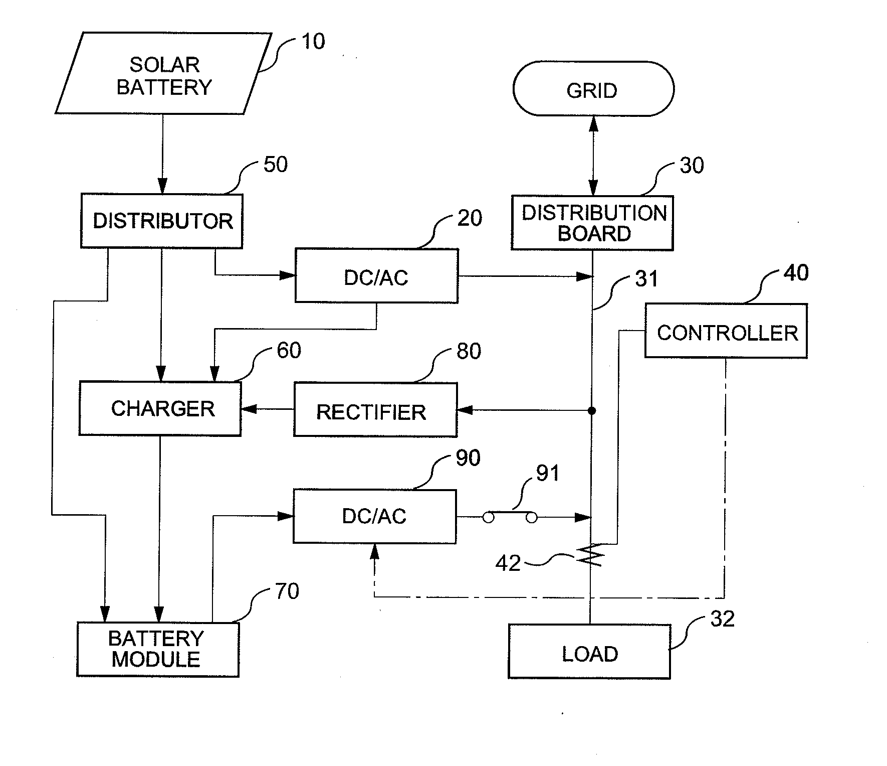
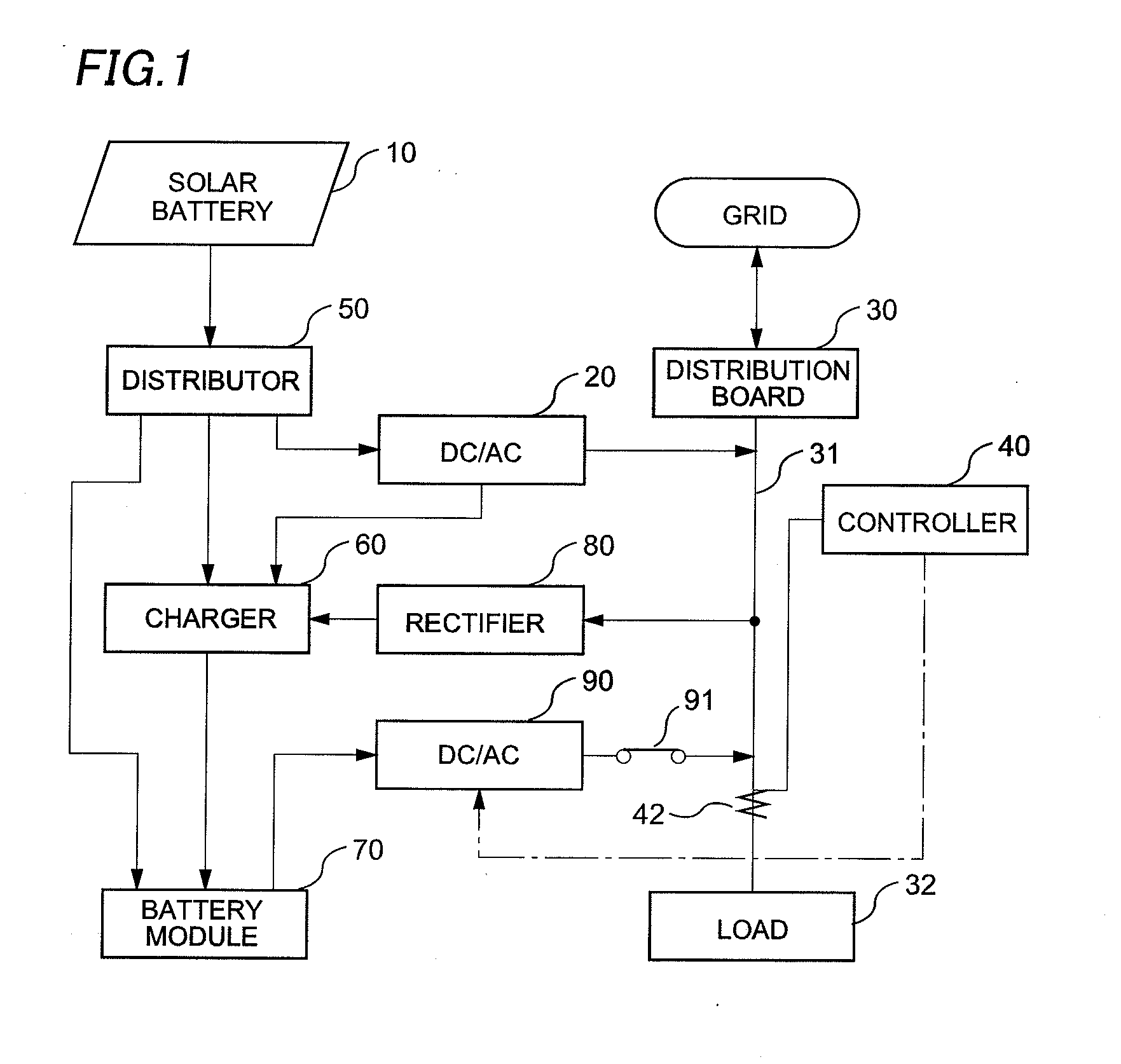
[0026]FIG. 1 shows an outline of an overall battery system according to a first embodiment of this invention. A solar battery 10 shown in FIG. 1 is formed of a plurality of solar battery cells connected in series.

[0027]DC power generated by the solar battery 10 is supplied to a distributor 50 and then selectively supplied either to a DC / AC converter for solar battery (referred to as a solar inverter) 20 or to a charger 60. The DC / AC converter for solar battery 20 converts the DC power into AC power of predetermined frequency before being superimposed on an indoor alternating current branch 31. The indoor alternating current branch 31 is connected to a power grid through a distribution board 30 having an electric current breaker and the like. ...


PUM

PropertyMeasurementUnit
frequencyaaaaaaaaaa
frequencyaaaaaaaaaa
frequencyaaaaaaaaaa

Abstract

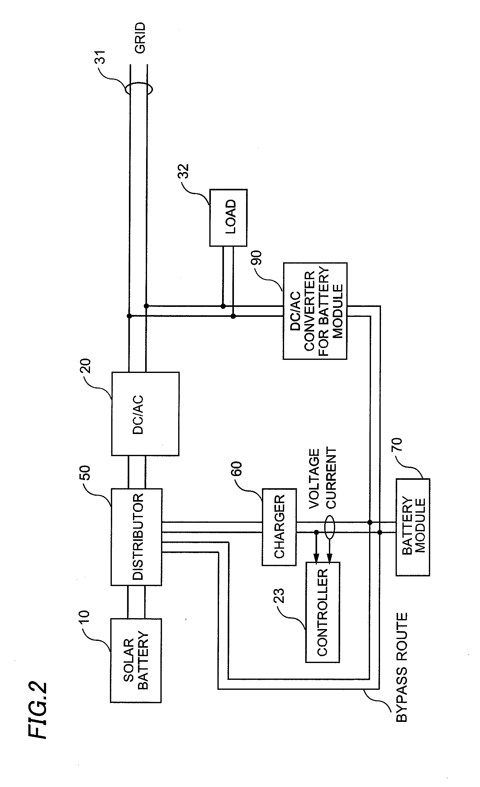
This invention offers an battery system that reduces a conversion loss due to a charger to reduce power consumption. The battery system has a solar battery, a battery module, a bypass route to bypass a charger to charge the battery module with DC power generated by the solar battery, and a control unit to control so that the electric power generated by the solar battery is supplied to the battery module through the bypass route when an output voltage of the solar battery is equal to or higher than a first predetermined voltage, that is higher than a terminal voltage of the battery module, and equal to or lower than a second predetermined voltage.

Description

CROSS-REFERENCE OF THE INVENTION[0001]This application claims priority from Japanese Patent Application No. 2010-54256 and No. 2010-142130, the content of which are incorporated herein by reference in their entirety.BACKGROUND OF THE INVENTION[0002]1. Field of the Invention[0003]This invention relates to a battery system, specifically to a battery system provided with a generator using a renewable energy as a solar battery, a DC / AC converter, a battery module and the like.[0004]2. Description of the Related Art[0005]This kind of the battery system is to provide a load with electric power by superimposing electric power generated by a solar battery or electric power discharged from a battery module on an indoor alternating current branch, which is supplied electric power from a commercial power grid. Power consumption from the grid can be reduced by an amount of the generated or discharged electric power, and maximum electric power to be supplied from the grid can be reduced as well....

Claims


Application Information

Patent Timeline
Patent Type & Authority Applications(United States)
IPC IPC(8): H01M10/46
CPCY02E10/566H02J7/35Y02E10/56
Inventor UEHASHI, HIROYUKIKUBO, MAMORUSARUHASHI, KOICHISHIMAYAMA, HAJIME
Owner SANYO ELECTRIC CO LTD
Learn More