
DC to DC converter having switch control and method of operation

Active Publication Date: 2011-09-15
NXP USA INC
View PDF5 Cites 9 Cited by
  • Summary
  • Abstract
  • Description
  • Claims
  • Application Information

AI Technical Summary

Problems solved by technology

Typically a diode is used in the conversion process but any current passing through the diode is a loss of power due to the voltage drop of about 0.7 volt of a forward biased PN junction.
Attempts have been made to eliminate this diode drop by using a switched transistor, but timing of the transistor is very critical for proper operation.
If the transistor is becomes non-conductive too soon, power is wasted through the diode.

Method used


Image

  • DC to DC converter having switch control and method of operation
  • DC to DC converter having switch control and method of operation
  • DC to DC converter having switch control and method of operation

Examples


Embodiment Construction

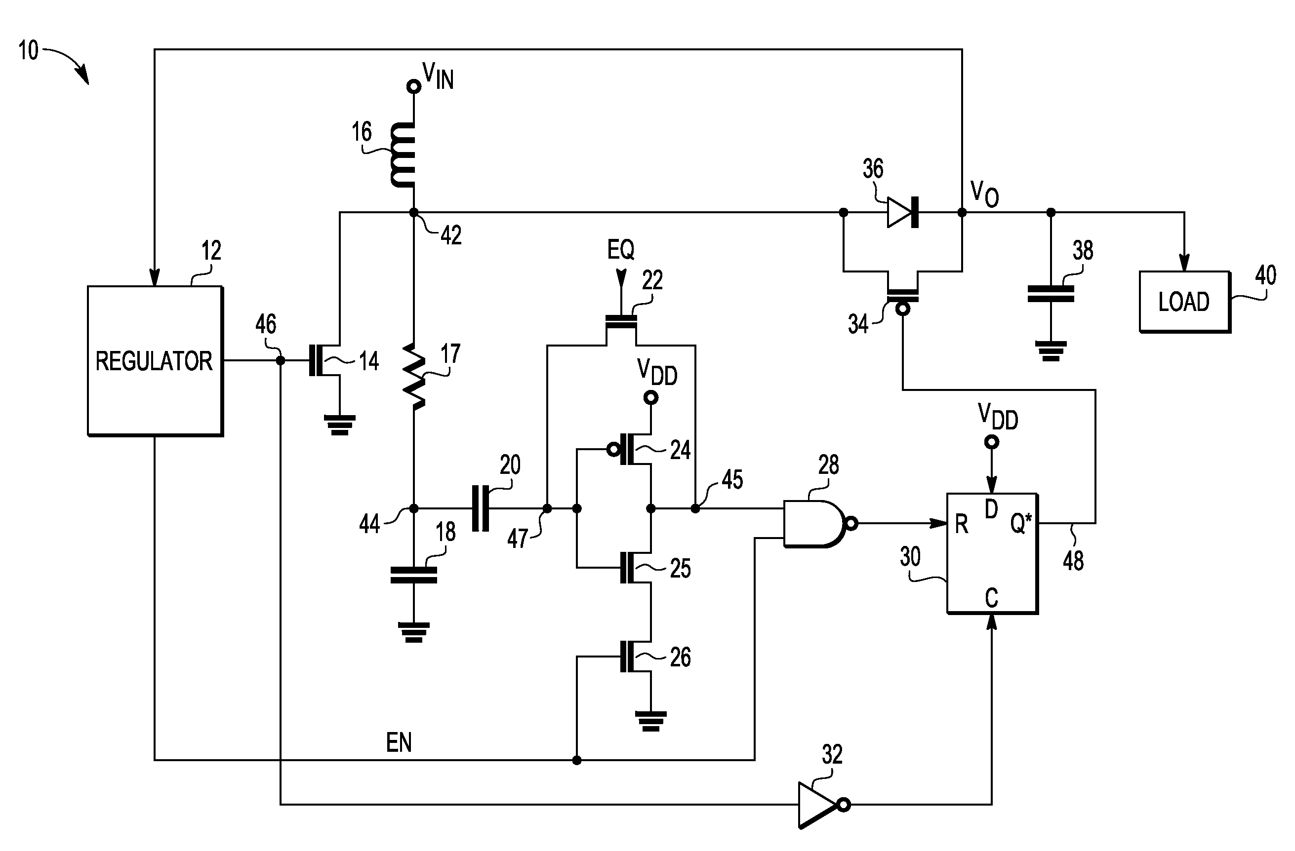
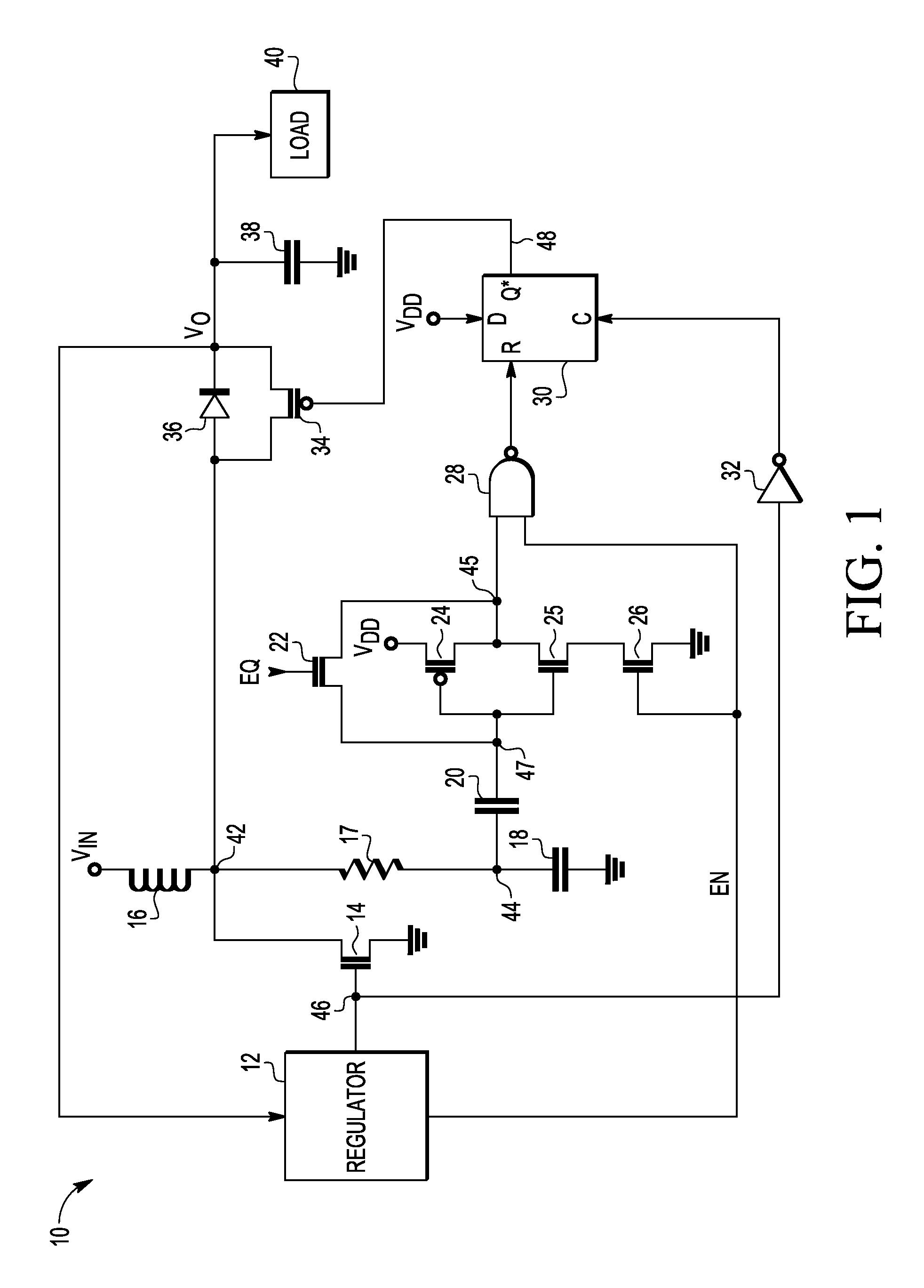
[0011]In one aspect a DC to DC converter has a switch in parallel with a diode that is used to bypass the diode to improve efficiency. Connections are present for an inductor in which current is to be passed through the inductor and corresponding energy stored in the inductor which lasts for a first duration. The energy, in the form of current, is then coupled through the diode and, after a very short delay, through the switch to provide current at the output voltage. The timing of the switch becoming non-conductive is important to the efficiency of the converter and is achieved using an RC integrator that computes both the time of storing energy in the inductor and the time that the inductor provides current to the output. This is better understood by reference to the following description and the drawings.

[0012]The terms “assert” or “set” and “negate” (or “deassert” or “clear”) are used herein when referring to the rendering of a signal, status bit, or similar apparatus into its l...


PUM


Abstract

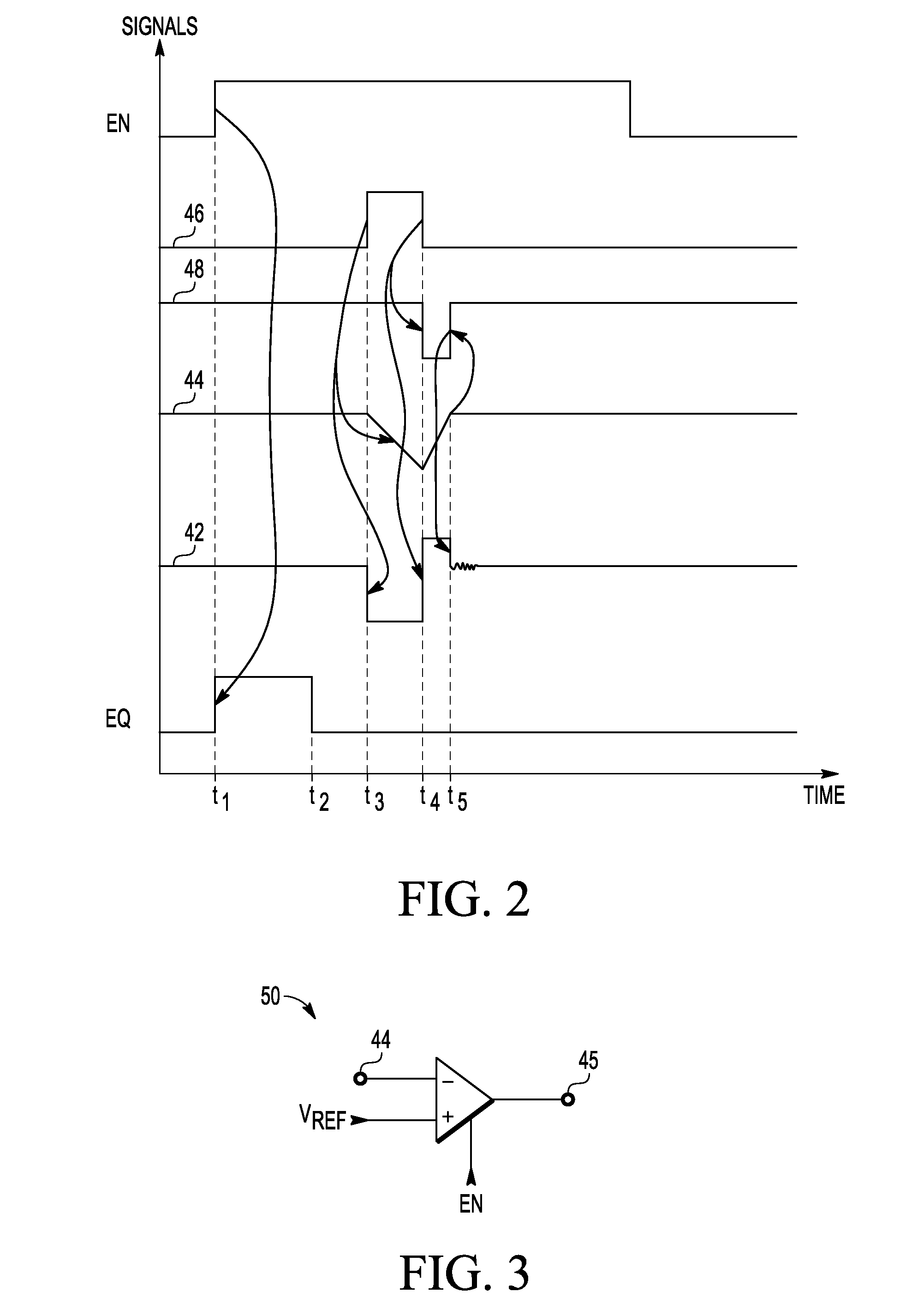
In a D.C. to D.C. converter, an input voltage is received via an inductor at an input terminal and stored onto a capacitor of an integrator. A first switch is coupled between the input terminal and a reference terminal such as ground and thereby fluxes the inductor. The input voltage stored on the capacitor falls at a rate determined by the integrator circuit and an initial value of the input voltage. After a time duration, the first switch becomes nonconductive. Current flows from the inductor through a diode to an output terminal until a second switch across the diode is made conductive. Stored voltage on the capacitor of the integrator increases in response to the second switch being conductive. The stored voltage on the capacitor is continuously compared with a reference voltage. The second switch is made nonconductive when the stored voltage on the capacitor exceeds the reference voltage.

Description

RELATED APPLICATION[0001]This application is related to US application docket number RA48549ZC, titled “DC to DC CONVERTER HAVING ABILITY OF SWITCHING BETWEEN CONTINUOUS AND DISCONTINUOUS MODES AND METHOD OF OPERATION,” by Pigott et al., assigned to the assignee hereof, and filed on even date herewith.BACKGROUND[0002]1. Field[0003]This disclosure relates generally to DC to DC to converters, and more specifically, to DC to DC converters having switch control.[0004]2. Related Art[0005]DC to DC converters have an important role in systems because it is not uncommon for the power supply that is available to have a wide voltage range. Because the power supply may be a battery, it is desirable that the DC to DC converter perform its conversion efficiently. Efficiency is reduced by any power used by the DC to DC converter itself. Thus, for increasing efficiency, it is desirable to eliminate or reduce any power consumed during the conversion. Typically a diode is used in the conversion proc...

Claims


Application Information

Patent Timeline
IPC IPC(8): G05F1/10
CPCY02B70/1466H02M3/1588Y02B70/10
Inventor PIGOTT, JOHN M.
Owner NXP USA INC
Learn More