
Optical scanner and image forming apparatus

an image forming apparatus and optical scanner technology, applied in the field of optical scanners and image forming apparatuses, can solve the problems of uneven refractive index distribution, uneven birefringence distribution of molded plastic scanning lenses, and difference in thickness

Inactive Publication Date: 2011-09-15
RICOH KK
View PDF3 Cites 10 Cited by
  • Summary
  • Abstract
  • Description
  • Claims
  • Application Information

AI Technical Summary

Benefits of technology

[0033]It is an object of the present invention to at least partially solve the problems in the conventional technology.

Problems solved by technology

In a molded plastic scanning lens, the refractive index distribution tends to be uneven.
Many scanning lenses are larger in size than pickup lenses (objective lenses), for example, used in an optical disk apparatus, and some molded plastic scanning lenses have an uneven birefringence distribution.
In particular, a larger difference in thickness between the center and the peripherals of a lens, that is, a greater difference in thickness leads to more uneven birefringence distribution.
If the amounts of light on the scanned surface are different depending on the light emitters, the concentration of an output image might become uneven, and especially, banding might occur.
If a refractive index distribution is uneven, because the refractive power becomes different depending on a beam path, the light emitters have different focal points on the scanned surface, disadvantageously.
As a result, the amount of exposure on the scanned surface would be different for each of the light emitters, disadvantageously.
Furthermore, the effect of the uneven birefringence distribution is not considered in the optical scanners disclosed in Japanese Patent No. 3518765 and Japanese Patent Application Laid-open No. 2009-3393.
However, when a noise is generated, the pulse waveform of the optical output is disturbed to change the amount of light emission.
In such a case, a predetermined output cannot be obtained from an input current, and that results in an uneven density of the image.
Thus, in a VCSEL, returning light is highly likely to interfere with the light inside of the resonator, and therefore, a noise is highly likely to be produced.
However, when a quarter-wave plate is used, the circularly polarized light becomes incident on the plastic-molded scanning lens, and that will worsen the problem of the birefringence.
Inability of correcting such variation results in an uneven density in an output image.

Method used


Image

  • Optical scanner and image forming apparatus
  • Optical scanner and image forming apparatus
  • Optical scanner and image forming apparatus

Examples


Embodiment Construction

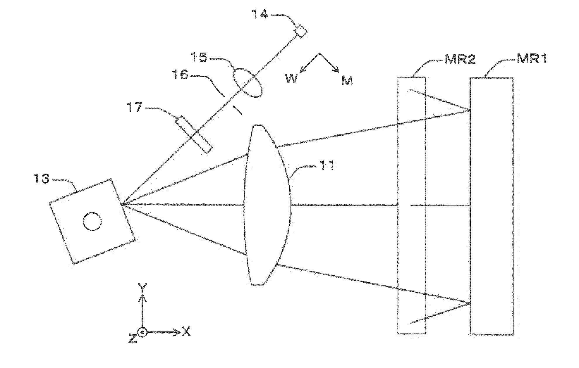
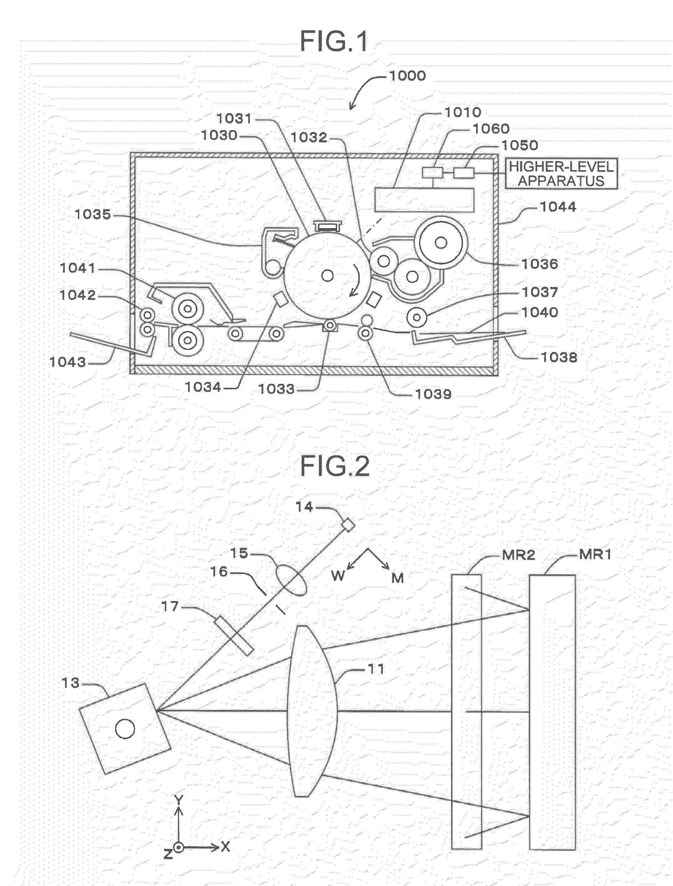
[0086]Exemplary embodiments of the present invention are explained below with reference to FIGS. 1 to 37. FIG. 1 is a schematic of a laser printer 1000 as an image forming apparatus according to an embodiment of the present invention.

[0087]The laser printer 1000 includes an optical scanner 1010, a photosensitive drum (photosensitive element) 1030, a charger 1031, a developing roller 1032, a transfer charger 1033, a neutralizing unit 1034, a cleaning unit 1035, a toner cartridge 1036, a paper feeding roller 1037, a paper feeding tray 1038, a registration roller pair 1039, a fixing rollers 1041, paper ejecting rollers 1042, a paper ejecting tray 1043, a communication controller 1050, and a printer controller 1060 that controls each of these units comprehensively. These units are housed in predetermined positions in a printer housing 1044.

[0088]The communication controller 1050 controls bidirectional communications with a higher level apparatus (e.g., a personal computer) via a network...


PUM


Abstract

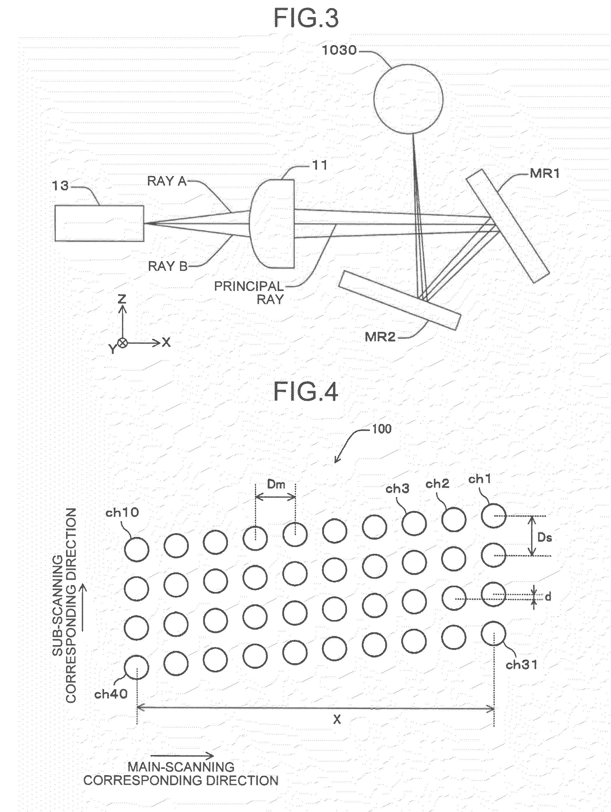
An optical scanner includes a light source, a deflector and a scanning optical system. The scanning optical system includes a first optical system including at least one resin scanning lens, and a second optical system between the target surface and one resin scanning lens. The second optical system includes at least one of a folding mirror(s) and a glass sheet(s), wherein m1+g2=m2+g1 is satisfied wherein m1 and g1 are respectively number of the folding mirror(s) and number of the glass sheet(s) to which the first ray has a shorter optical path than the second ray does, m2 and g2 are respectively number of the folding mirror(s) and number of the glass sheet(s) to which the first ray has a longer optical path than the second ray does.

Description

CROSS-REFERENCE TO RELATED APPLICATIONS[0001]The present application claims priority to and incorporates by reference the entire contents of Japanese Patent Application No. 2010-055509 filed in Japan on Mar. 12, 2010.BACKGROUND OF THE INVENTION[0002]1. Field of the Invention[0003]The present invention relates to an optical scanner and an image forming apparatus.[0004]2. Description of the Related Art[0005]In a digital copier, a laser printer, a laser facsimile, and the like, an image is written using an optical scanner. Such an optical scanner includes a light source having a light emitter, a first optical system that forms an image of a light beam output from the light source as a long linear image extending in a main-scanning direction, a deflector having a deflecting reflective surface disposed near a position where the linear image is formed to deflect a light beam output from the first optical system, and a second optical system that condenses a light beam deflected by the defl...

Claims


Application Information

Patent Timeline
Patent Type & Authority Applications(United States)
IPC IPC(8): B41J27/00
CPCG02B26/125B41J2/471
Inventor TATSUNO, HIBIKIICHII, DAISUKEARAI, NOBUYUKI
Owner RICOH KK
Learn More