Ophthalmological measuring device and measurement method

a measuring device and ophthalmological technology, applied in the field of ophthalmological measuring devices and ophthalmological measurement methods, can solve the problems of limited depth measurement range, limited number of measurement points, and movement artifacts caused by eye movements generating measurement errors, so as to reduce the impairment of measurement accuracy

Active Publication Date: 2011-09-15
SIS SURGICAL INSTR SYST
View PDF7 Cites 7 Cited by
  • Summary
  • Abstract
  • Description
  • Claims
  • Application Information

AI Technical Summary

Benefits of technology

[0010]It is an object of the present invention to propose an ophthalmological measuring device and an ophthalmological measurement method for determining geometric structures of an eye, which do not have at least some of the disadvantages of the known systems. More particularly, it is an object of the present invention to propose an ophthalmological measuring device and an ophthalmological measurement method for determining geometric structures of an eye, which, on the one hand, are not limited to the visible measurement region of known triangulating measurement methods and, on the other hand, have a reduced impairment of the measurement accuracy by movement artifacts compared to known interferometric methods.
[0012]More particularly, the aforementioned objects are achieved by the present invention by virtue of the fact that an ophthalmological measuring device for determining geometric structures of an eye, more particularly geometric structures in the region of the anterior chamber of the eye, includes an optical, triangulating first measurement system for determining at least one geometric reference in the eye by triangulation and an optical, interferometric second measurement system for determining (two- and / or three-dimensional) geometric detailed structures in the eye (particularly in the region of the anterior chamber of the eye) by optical interferometry, and by virtue of the fact that the measuring device is configured to register and store the geometric detailed structures determined by the second measurement system, and to position the geometric detailed structures, registered and stored by the measuring device, on the basis of the at least one geometric reference in the eye determined by the first measurement system. Since triangulating measurement systems, more particularly light-slit- (light-section-) based measurement systems, generate no or only insubstantial movement artifacts (for example, 30 to 60 light-slit recordings suffice for an overall topology of the cornea in triangulating measurement systems, whereas more than 500 axial measurements on 30 to 60 scan surfaces are needed for this in interferometric measurement), and since interferometric measurement systems can be designed for a detailed measurement region that is smaller compared to the measurement region of the triangulating measurement system but has a high optical resolution, the positioning of the geometric detailed structures in the eye on the basis of the geometric reference allows a particularly advantageous combination of triangulating and interferometric measurement methods. On the one hand, geometric detailed structures can be registered in the eye by the interferometric measurement system with a high optical resolution and at positions that are not visible to the triangulating measurement system, and, on the other hand, they can be positioned in the eye on the basis of geometric references, which are determined by the triangulating measurement system without significant movement artifacts. Hence, the advantages of the interferometric measurement system are combined with the advantages of the triangulating measurement system. The reduced impairment in respect of movement artifacts additionally allows the use of cost-effective, slower interferometric (OCT-) techniques (in particular time-domain OCT), which advantageously have greater depth measurement ranges and also allow the use of other wavelengths (in particular wavelengths>1000 nm).
[0013]In one embodiment variant, the first measurement system and the second measurement system are mechanically coupled such that the geometric detailed structures in the eye can be positioned on the basis of one or more geometric settings in a position of the first measurement system (11) corresponding to the geometric reference. In other words, the triangulating measurement system and the interferometric measurement system are set up in a mechanical / geometric fashion, preferably by means of a calibration body, for registering one or more defined geometric references of the eye and the geometric settings are determined from this defined geometric calibration position, which settings define a calibrated relationship between the triangulating measurement system and the interferometric measurement system and, in a defined position of the triangulating measurement system (with respect to the eye), allow a positioning of the geometric detailed structures determined by the interferometric measurement system. An advantage of this variant is that there is no need for an image registration and assignment of geometric structure features and positioning of the geometric detailed structures on the basis thereof if the geometric detailed structures are registered by the interferometric measurement system in prompt fashion (i.e. within a defined timeframe) with respect to the setting of the triangulating measurement system corresponding to the geometric reference.
[0014]In a further embodiment variant, the measuring device includes a positioning module designed to determine one or more geometric reference features of the eye and to position the geometric detailed structures on the basis of the geometric reference features in the eye. In other words, the geometric detailed structures are positioned in the eye on the basis of geometric reference features of the eye, which, on the one hand, are determined as a geometric reference by the triangulating measurement system and, on the other hand, are determined in the geometric detailed structures by the interferometric measurement system. An advantage of this variant is that a user does not need to undertake a mechanical / geometric set-up of the triangulating measurement system with respect to a defined geometric reference of the eye before the interferometric measurement system can register the geometric detailed structures as a result of this. That is to say the triangulating and the interferometric measurement methods can be carried out (temporally) independently of one another without bothersome influences of eye movements, that is to say both in parallel / simultaneously and sequentially and deferred.
[0018]In a further embodiment variant, the first scan module is designed to move the light slit by rotation about a rotational axis substantially running in the light slit, and the second scan module is designed to move the light beam in a scan plane, with a central projection axis of the second scan module forming an angle with the rotational axis or running along the rotational axis. Scanning the eye by rotating the light slit allows a particularly simple embodiment of the triangulating measurement system, without deflection mirrors or translational movement drivers.

Problems solved by technology

In triangulation methods and in interferometric methods with a single scanned beam, the movement artifacts caused by eye movements generate measurement errors, which have to be corrected by an additional method that registers the eye movements.
In turn, triangulation methods with many individual beams or with structured illumination are disadvantageous in that the number of measurement points is limited and, moreover, the depth measurement range is severely limited because the imaging unit cannot be arranged in Scheimpflug configuration for all beams.
The known triangulating measuring devices generally are disadvantageous in that the measurement region thereof that can be registered is limited to the front eye region (anterior chamber region), which can be illuminated directly, and the posterior chamber of the eye is not visible.
In the process, the measurement region of the known triangulating measuring devices is further limited by opacity, e.g. in the cornea, by implants, e.g. lenses placed in front, and by the iris, and certain partial regions, such as the anterior chamber angle, cannot, in general terms, be registered by the known triangulating measuring devices due to tissue properties.
Thus, as soon as the interferometric methods are used for the structural measurement at a plurality of positions, eye movements generate movement artifacts and hence measurement errors.
Moreover, compared to triangulating measurement methods in Scheimpflug configuration, there is the additional disadvantage that the depth measurement range of interferometric methods has to be designed to be significantly smaller at a high lateral resolution.
Since the focal depth region decreases disproportionately with image resolution for optical reasons, the desire for high lateral resolution generally significantly restricts the depth measurement range, particularly in interferometric methods.
However, disadvantages of these techniques include the high technical and financial expenditure required for this, a reduced resolution and / or compromises (limitations) in the depth measurement range.
It can be observed that there are no commercially available systems with movement- and artifact-free interferometric methods.

Method used


Image

  • Ophthalmological measuring device and measurement method
  • Ophthalmological measuring device and measurement method
  • Ophthalmological measuring device and measurement method

Examples


Embodiment Construction

ng measurement system and an interferometric measurement system of the ophthalmological measuring device.

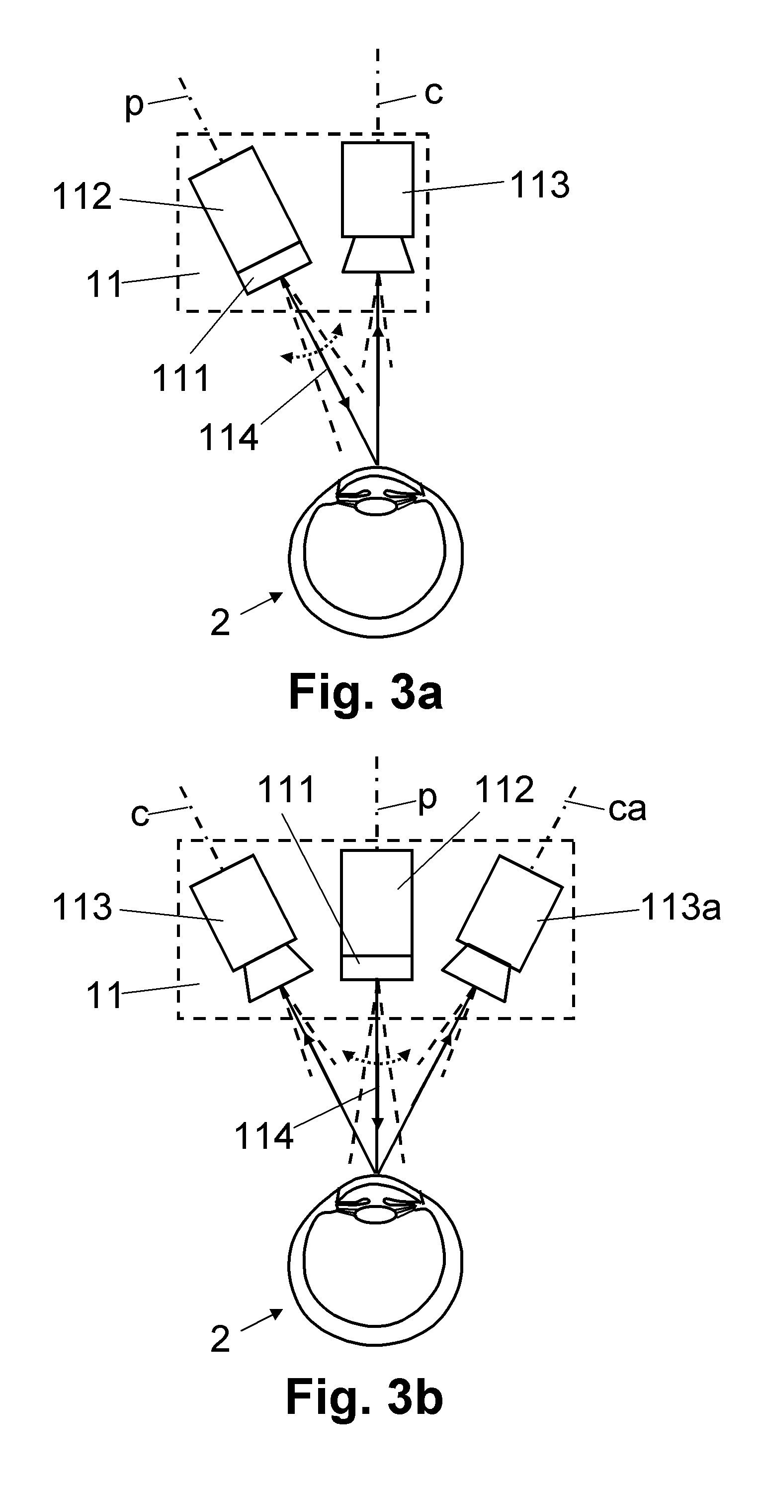
[0035]FIG. 7 shows a block diagram that schematically illustrates a further rotatable arrangement of a triangulating measurement system and an interferometric measurement system of the ophthalmological measuring device.

[0036]FIG. 8 shows a block diagram that schematically illustrates a scan plane of the interferometric measurement system, which plane is situated in the plane of the light slit of the triangulating measurement system.

[0037]FIG. 9 shows a block diagram that schematically illustrates a further arrangement of the interferometric measurement system, in which the scan plane of the interferometric measurement system is situated in the plane of the light slit of the triangulating measurement system.

[0038]FIG. 10 shows a cross-sectional diagram that schematically illustrates a detailed measurement region of the interferometric measurement system, which region can move in t...


PUM


Abstract

An ophthalmological measuring device for determining geometric structures in an eye includes an optical, triangulating measurement system for determining at least one geometric reference in the eye by triangulation, and an optical, interferometric measurement system for determining geometric detailed structures in the eye by optical interferometry. The measuring device is designed to position the geometric detailed structures determined by the interferometric measurement system on the basis of the at least one geometric reference in the eye determined by the triangulating measurement system. This firstly allows the interferometric measurement system to register geometric detailed structures in the eye with a high optical resolution and at places that are not visible to the triangulating measurement system, and secondly allows the positioning of said geometric detailed structures in the eye on the basis of geometric references that are determined by the triangulating measurement system without significant movement artifacts.

Description

CROSS REFERENCE TO RELATED APPLICATIONS[0001]The present application is a continuation application of U.S. patent application Ser. No. 12 / 850,175 filed Aug. 4, 2010 entitled OPHTHALMOLOGICAL MEASURING DEVICE AND MEASUREMENT METHOD which claims benefit of and priority to U.S. Provisional Patent Application Ser. No. 61 / 231,459 filed Aug. 5, 2009 entitled OPHTHALMOLOGICAL MEASURING DEVICE AND MEASUREMENT METHOD, the entire contents of which are hereby incorporated by reference herein.BACKGROUND[0002]1. Field of the Disclosure[0003]The present disclosure relates to an ophthalmological measuring device and an ophthalmological measurement method for determining geometric structures of an eye. In particular, the present invention relates to an ophthalmological measuring device and an ophthalmological measurement method for determining geometric structures of an eye, in which use is made of an optical, triangulating first measurement system and an optical, interferometric second measurement...

Claims


Application Information

Patent Timeline
Patent Type & Authority Applications(United States)
IPC IPC(8): A61B3/10
CPCG06K9/00604A61B3/1005G06V40/19
Inventor RATHJEN, CHRISTIAN
Owner SIS SURGICAL INSTR SYST
Why Eureka
Try Eureka