Varifocal lens and liquid filling method for manufacturing same

Inactive Publication Date: 2011-09-15
FUJIFILM CORP
View PDF9 Cites 8 Cited by
  • Summary
  • Abstract
  • Description
  • Claims
  • Application Information

AI Technical Summary

Benefits of technology

[0011]The present invention has been contrived with the foregoing circumstances in view, an object thereof being to provide a varifocal lens whereby it is possible to prevent external leaking of liquid from inside the lens, even when the lens is moved, to prevent the liquid inside the lens from coming into contact with the air and evaporating, and to suppress residual vibration of the liquid lens (interface), and it is a further object of the invention to provide a liquid filling method for use in manufacturing the varifocal lens.

Problems solved by technology

Since a general varifocal lens moves the position of a lens which constitutes an optical system and therefore requires a stroke corresponding to the amount of variation of the focal length, it takes time to move the lens and is restricted in terms of the speed of response.
Since the response speed of the optical system is extremely slow compared to the time required for image capture in an imaging element, or the image processing time, the optical system presents a bottle neck in the overall system, and therefore high-speed response is demanded in a varifocal lens.
However, according to the composition in Japanese Patent Application Publication No. 2008-152090, two micro-pumps are required, and therefore the overall size of the lens apparatus becomes large.
Furthermore, since the second micro pump serves as a damper or a spring with respect to change in the volume of the first micro pump, then residual vibration may arise at the liquid interface which constitutes the lens.
In order to eliminate residual vibration at the liquid interface which constitutes the lens, the amount of change in the second micro pump is required to be controlled actively so as to absorb the change in the volume of the first micro pump, and such control is complicated.

Method used


Image

  • Varifocal lens and liquid filling method for manufacturing same
  • Varifocal lens and liquid filling method for manufacturing same
  • Varifocal lens and liquid filling method for manufacturing same

Examples


modification example 1

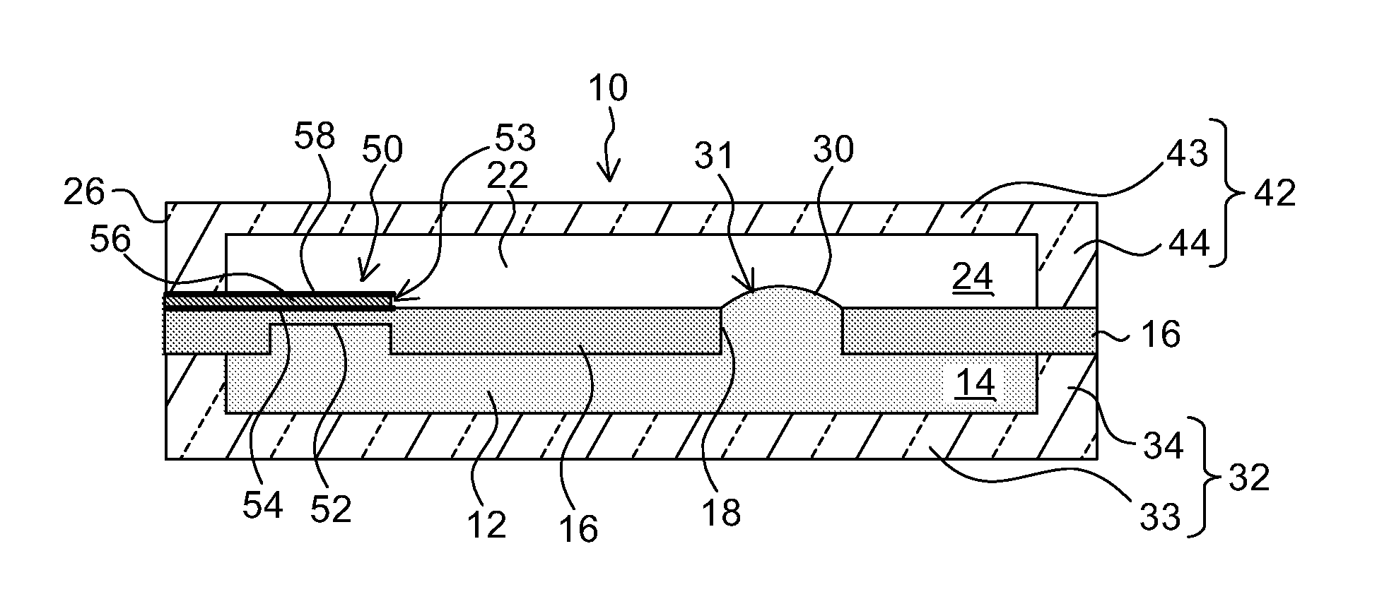
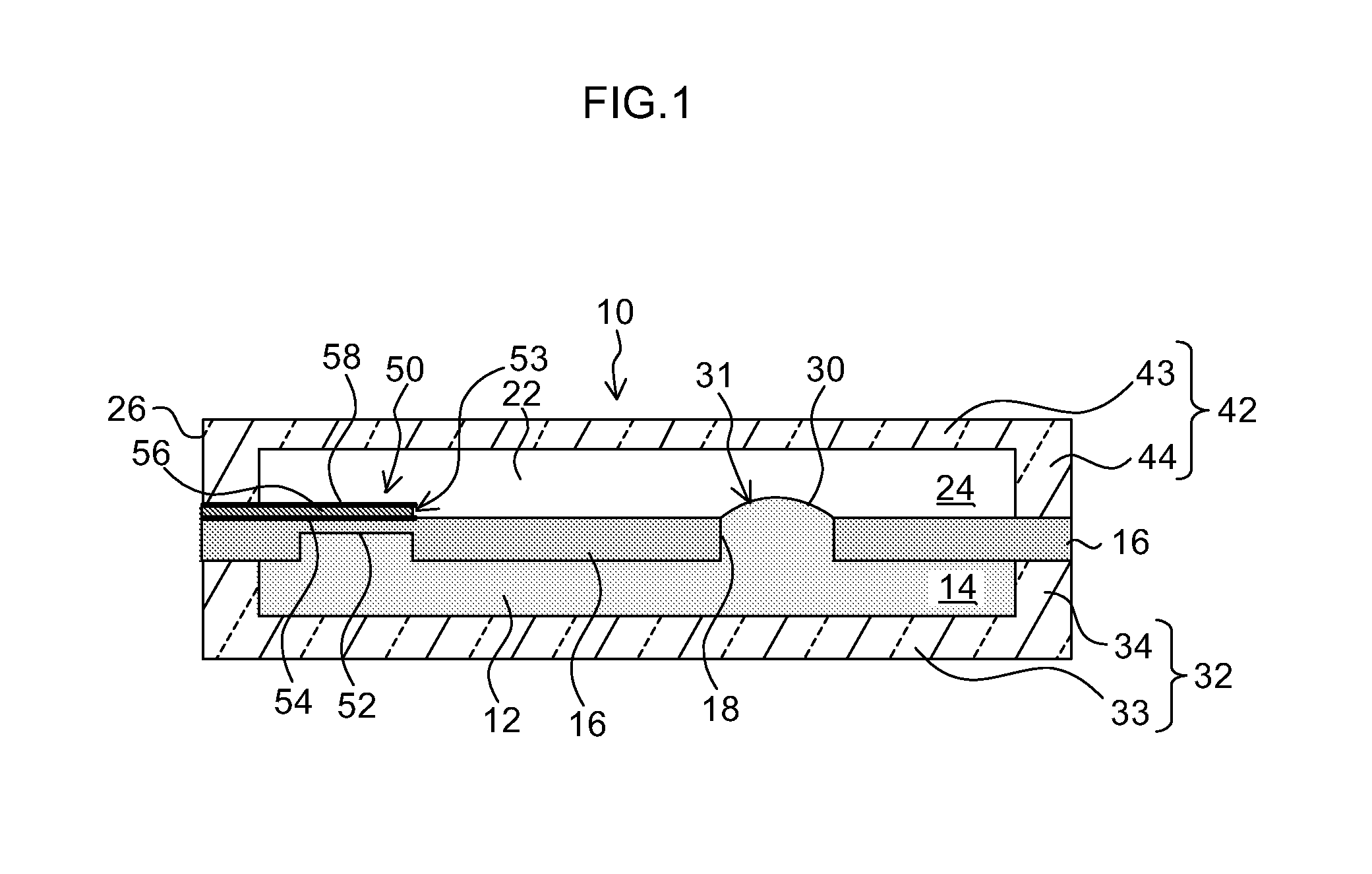
[0073]In the present embodiment, the whole of the bottom plate member 33 and the ceiling plate member 43 is made from light-transmitting members, but it is also possible to form light-transmitting window sections in portions of the bottom plate member 33 and the ceiling plate member 43. For example, it is possible to form through holes in a portion of the bottom plate member 33 and in a portion of the ceiling plate member 43, and to fill a transparent glass or a transparent resin into the portion of these through holes.

modification example 2

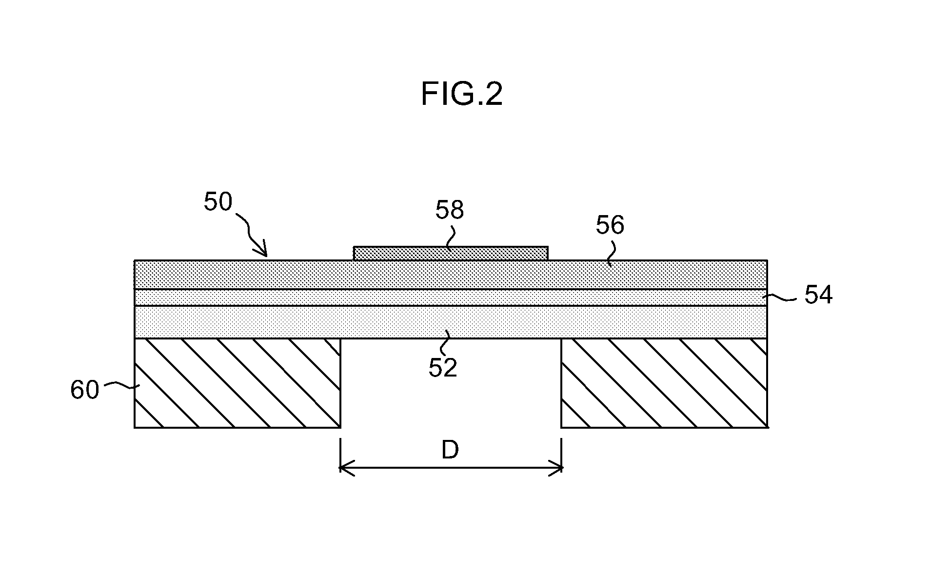
[0074]In the embodiment described above, only one piezoelectric actuator 50 is provided inside the sealed vessel 26, but it is also possible to adopt a mode in which a plurality of piezoelectric actuators are provided. For example, by providing a plurality of diaphragm-type piezoelectric actuators in a portion of the partition plate and driving these actuators simultaneously, it is possible to obtain a larger volume change and hence to increase the range of variation of the focal length.

Example of Application of the Varifocal Lens According to the Present Invention

[0075]A varifocal lens according to embodiments of the present invention is capable of high-speed response and has high spatial resolving power, and therefore is suitable for high-speed three-dimensional scanners and omnifocal microscope systems, and the like, and is capable of high-speed tracking of moving objects. Furthermore, by miniaturization, the lens can also be mounted in an electrical device, such as a portable te...


PUM

PropertyMeasurementUnit
Lengthaaaaaaaaaa
Volumeaaaaaaaaaa
Deformation enthalpyaaaaaaaaaa

Abstract

A varifocal lens which uses an interface between a first fluid and a second fluid that are mutually immiscible, as a light refracting surface, includes: a sealed vessel in which a first chamber into which the first fluid is filled is connected via an opening to a second chamber into which the second fluid is filled; and an elastic deformation section which is provided in elastically deformable fashion in a portion of a partition wall that divides the first chamber and the second chamber in the sealed vessel and which deforms in contact with both the first fluid filled into the first chamber and the second fluid filled into the second chamber, wherein: a lens section having the interface is formed in the opening, and a focal length of the lens section is changed by causing the interface to deform through altering volumes of the first chamber and the second chamber in mutually opposite directions by deformation of the elastic deformation section.

Description

BACKGROUND OF THE INVENTION[0001]1. Field of the Invention[0002]The present invention relates to a varifocal lens of which the focal length can be varied and controlled, and in particular, to a structure of a small varifocal lens suited to high-speed response which uses a liquid interface as a refractive surface, and to a liquid filling method employed when manufacturing the varifocal lens.[0003]2. Description of the Related Art[0004]Since a general varifocal lens moves the position of a lens which constitutes an optical system and therefore requires a stroke corresponding to the amount of variation of the focal length, it takes time to move the lens and is restricted in terms of the speed of response. From a view point of measuring external information, for instance, in a vision sensor, or the like, the response speed of a varifocal lens which moves the lens itself is very slow. Since the response speed of the optical system is extremely slow compared to the time required for image...

Claims


Application Information

Patent Timeline
IPC IPC(8): G02B3/14B65B3/04
CPCG02B3/14
Inventor HIRABAYASHI, YASUTOSHI
Owner FUJIFILM CORP
Why Eureka
Try Eureka