Edge orientation for second derivative edge detection methods

Active Publication Date: 2011-09-15
ANALOG DEVICES INC
View PDF12 Cites 22 Cited by
  • Summary
  • Abstract
  • Description
  • Claims
  • Application Information

AI Technical Summary

Benefits of technology

[0010]The present invention and its exemplary embodiments are directed toward an improved method for processing images that utilizes the second order derivative of the intensity distribution function of the image or pixels of the image to identify edges and the orientation of those identified ed

Problems solved by technology

In particular, utilizing the first order derivative tends to produce thick edges.
For many reasons, some of which are beyond the scope of this disclosure, thick edges increase the complexity in downstream software which constructs contours (i.e., edge pixels assembled to define a line or curve), and are undesirable when attempting to identify objects in an image.
For example, it is extremely difficult and some times impossible to find the center of a thick edge.
However, post-processing requires extra hardware, and the images cannot be processed in “rea

Method used


Image

  • Edge orientation for second derivative edge detection methods
  • Edge orientation for second derivative edge detection methods
  • Edge orientation for second derivative edge detection methods

Examples


Example

[0041]Described herein are various exemplary embodiments of methods and systems consistent with the invention. These embodiments are exemplary and should not be interpreted to limit the scope one of ordinary skill would give to the invention.

The Algorithm

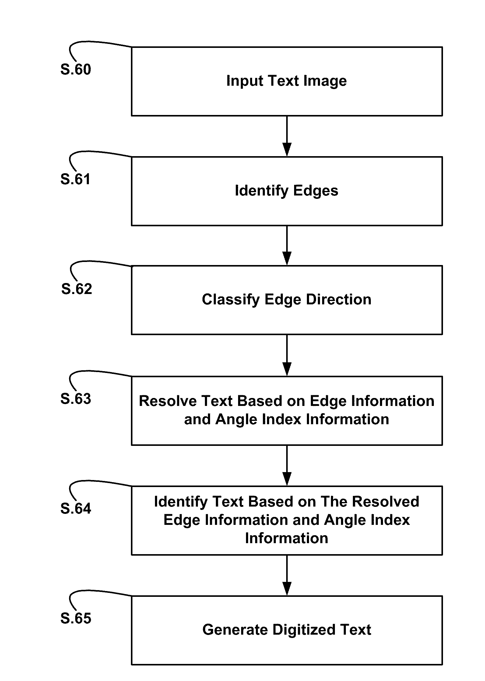
[0042]An exemplary embodiment of an algorithm for determining edge orientation information from the second order derivative of an intensity distribution function of an image is illustrated in FIG. 4. First, for each identified edge identify transitions (zero-crossings) in the horizontal direction in the intensity distribution, that is, identify low to high transitions and high to low transitions in the direction of the x-axis (S.1). Next, for each identified edge identify transitions (zero-crossings) in the vertical direction in the intensity distribution, that is, identify low to high transitions and high to low transitions in the direction of the y-axis (S.2). For each identified edge, identify the orientation of the edge based on...


PUM


Abstract

An improved algorithm for edge detection is provided that utilizes the second order derivative of the intensity distribution function of an image to provide edge orientation information for the detected edges. An exemplary embodiment of the improved algorithm includes determining the second order derivative of the intensity distribution function, identifying zero-crossings in the horizontal and vertical directions, assigning angle information to the identified zero-crossings in the horizontal and vertical directions; and identifying an edge orientation based the assigned angle information for the horizontal and vertical zero-crossing of the edge and adjacent edges.

Description

TECHNICAL FIELD[0001]Embodiments of the invention generally relate to image processing, and more particularly to the detection of edges in two-dimensional images based on changes in the gradient of intensity of the images.BACKGROUND[0002]Images are commonly thought of as two-dimensional representations of three-dimensional objects. Images may be defined by a two-dimensional grid, where each element of the grid is referred to as a pixel. Associated with each pixel is an intensity. The magnitude of pixel intensity is often expressed in terms of luminance. In a digital image, each pixel may be assigned a luminance value. In an 8-bit image that value would be 0 to 255. Dark pixels have a low intensity, while light pixels have a high intensity. FIG. 1a illustrates an image where the intensity of the image increases along the horizontal axis (from left to right). FIG. 1b is a graph of the intensity distribution of the image along the x-axis. This graph illustrates a change from low (black...

Claims


Application Information

Patent Timeline
IPC IPC(8): G06K9/60
CPCG06T7/0085G06T7/13
Inventor KARANAM, GOPALKUSSTATSCHER, BENNO
Owner ANALOG DEVICES INC
Why Eureka
Try Eureka