

Charging device
- Summary
- Abstract
- Description
- Claims
- Application Information
AI Technical Summary
Benefits of technology
Problems solved by technology
Method used
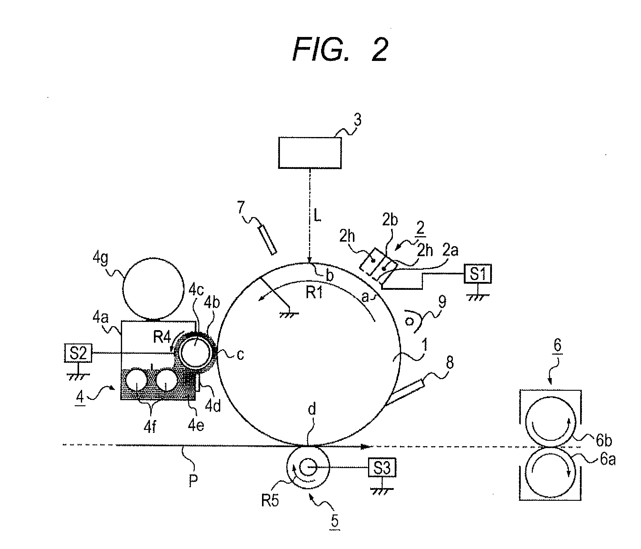
Image

Examples
experimental example 1
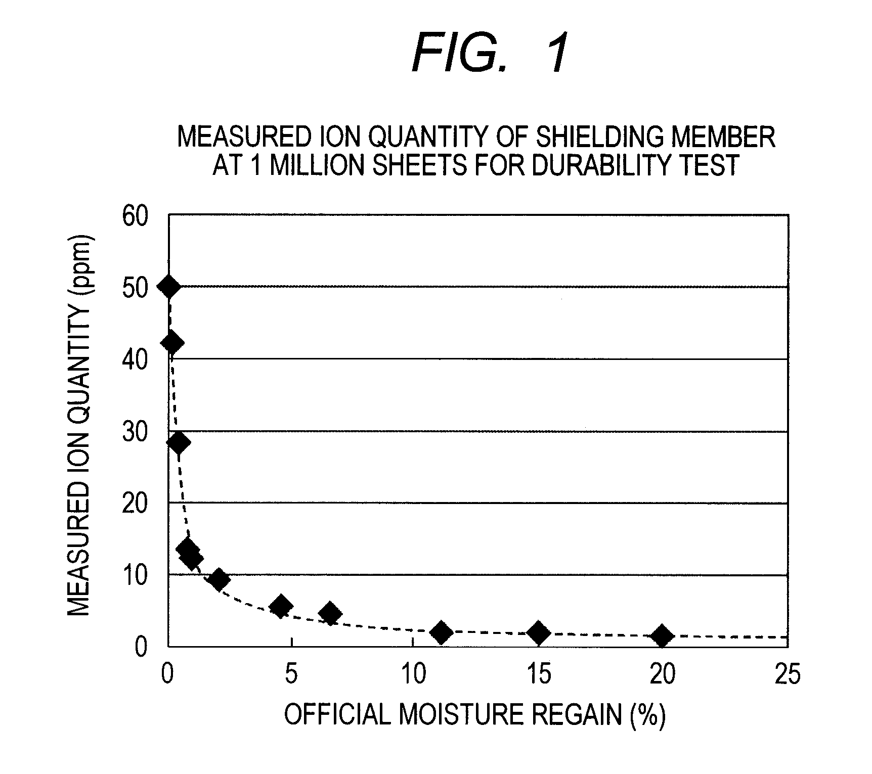
Evaluation Method for Amount of Adsorbed Material Originating from Electric Discharge Product onto Charger Shutter
[0121]A charger shutter member with the thickness of 250 μm formed from a material shown in the following Table 1 was mounted in the charging device of the above described image forming apparatus, as a charger shutter.
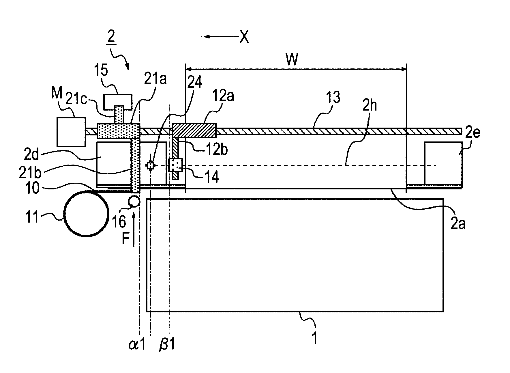
[0122]Then, images corresponding to 5,000 sheets of paper with the A4 size were output in 8 hours under the environment of the temperature of 30° C. and the relative humidity of 80%, while the state of FIG. 3 was kept. After that, the charger shutter member was left at rest for 16 hours in the state of FIG. 4. Such operations of outputting the images and leaving the charger shutter member at rest were repeated until the total number of the sheets of the output image reached 1 million sheets.
[0123]The charging region by the corona charger 2 in the present Experimental Example was 322 mm in the longitudinal direction (W in FIG. 3) and was 44 mm in the rotativ...
experimental example 2
[0137]The same evaluation as in Experimental Example 1 (however, except for evaluation for “swelling and deformation of fibers”) was conducted by using an image forming apparatus that used respective shielding members formed from the materials and having the forms shown in Table 2. The results are shown in Table 2.
TABLE 2Number of sheets for durability testOfficial250,000 Sheets500,000 Sheets1 Million sheetsmoistureIonIonIonExperimentalregainquantityImagequantityImagequantityImageExample No.Shielding member(%)(ppm)deletion(ppm)deletion (ppm)deletion2-1PE film0.03.5B14.0C55.3C2-2PE woven fabric0.03.1A12.4C49.2C2-3PET film0.13.0B12.0C48.2C2-4PET nonwoven0.12.6A10.5B42.1Cfabric2-5Acrylic film2.01.0A4.0B16.3C2-6Acryl woven2.00.6A2.4A9.5Bfabric2-7Nylon film4.50.6A2.6B10.4B2-8Nylon nonwoven4.50.4A1.5A6.0Bfabric
[0138]As shown in Table 2, it is understood that the amounts of the electric discharge products detected from the nonwoven fabrics and woven fabrics employed as the base material fo...
experimental example 3
[0140]The same evaluation as in Experimental Example 2 was conducted by using an image forming apparatus that used respective PET films as the charger shutter, which had the thickness of 250 μm and had various metals shown in Table 3 vapor-deposited or plated thereon. The results are shown in Table 3.
TABLE 3Number of sheets for durability test250,000 Sheets500,000 Sheets1 Million sheetsIonIonIonExperimentalquantityImagequantityImagequantityImageExample No.Shielding member(ppm)deletion(ppm)deletion(ppm)deletion3-1PET film3.0B12.0C48.2C3-2Aluminum vapor-deposited0.4A1.6B6.3BPET film3-3Zinc vapor-deposited PET0.4A1.6B6.5Bfilm3-4Tin vapor-deposited PET0.4A1.7B6.9Bfilm3-5Lead vapor-deposited PET0.4A1.8B7.2Cfilm3-6Brass-plated PET film0.6A2.3B9.1B3-7Bronze-plated PET film0.6A2.4B9.5B3-8Copper vapor-deposited0.7A2.7B10.8BPET film3-9Iron vapor-deposited PET1.0A3.8B15.3Cfilm3-10Nickel vapor-deposited1.0A4.0B16.2CPET film3-11Stainless sheet2.5B9.9B39.8C3-12Glass sheet4.7B18.8C75.4C3-13Ceramic...
PUM
 Abstract
Description
Claims
Application Information