Image recording apparatus

a recording apparatus and image technology, applied in the field of image recording apparatus, can solve the problems of large floor space required for recording apparatus and large space required for its installation, and achieve the effects of reducing height dimension, large vertical dimension, and convenient maintenance of apparatus

Active Publication Date: 2011-09-15
BROTHER KOGYO KK
View PDF6 Cites 13 Cited by
  • Summary
  • Abstract
  • Description
  • Claims
  • Application Information

AI Technical Summary

Benefits of technology

[0012]There is also a requirement for compact construction of the image recording apparatus with a reduced height dimension of the main body housing. The image recording apparatus of the type having the image reading device disposed in the upper part of the main body housing is usually constructed such that the image reading device is hinged to the main body housing so as to be opened and closed with respect to the upper surface of the housing, for easy maintenance of the apparatus. In this construction, it is actually difficult to form the above-indicated accommodation recess so as to extend above the image reading device. In this respect, the rear portion of the main body housing in which the accommodation recess is formed tends to have a large vertical dimension, resulting in a large bulk of the image recording apparatus.
[0013]The present invention was made in view of the background art described above. It is therefore a first object of the present invention to provide a compact image recording apparatus having a reduced vertical dimension of its m

Problems solved by technology

However, the both types of known image recording apparatus described above have a problem of a large floor space required for its installation due to the first manual medium insertion tray which is disposed with f

Method used


Image

  • Image recording apparatus
  • Image recording apparatus
  • Image recording apparatus

Examples


first embodiment

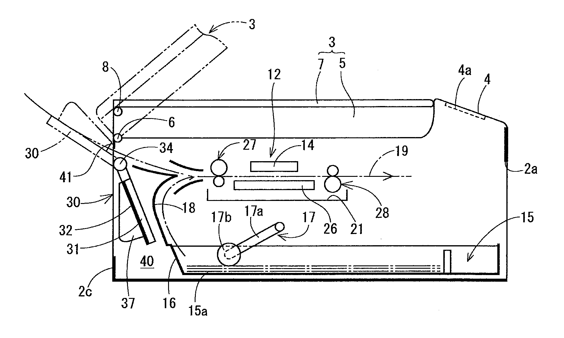
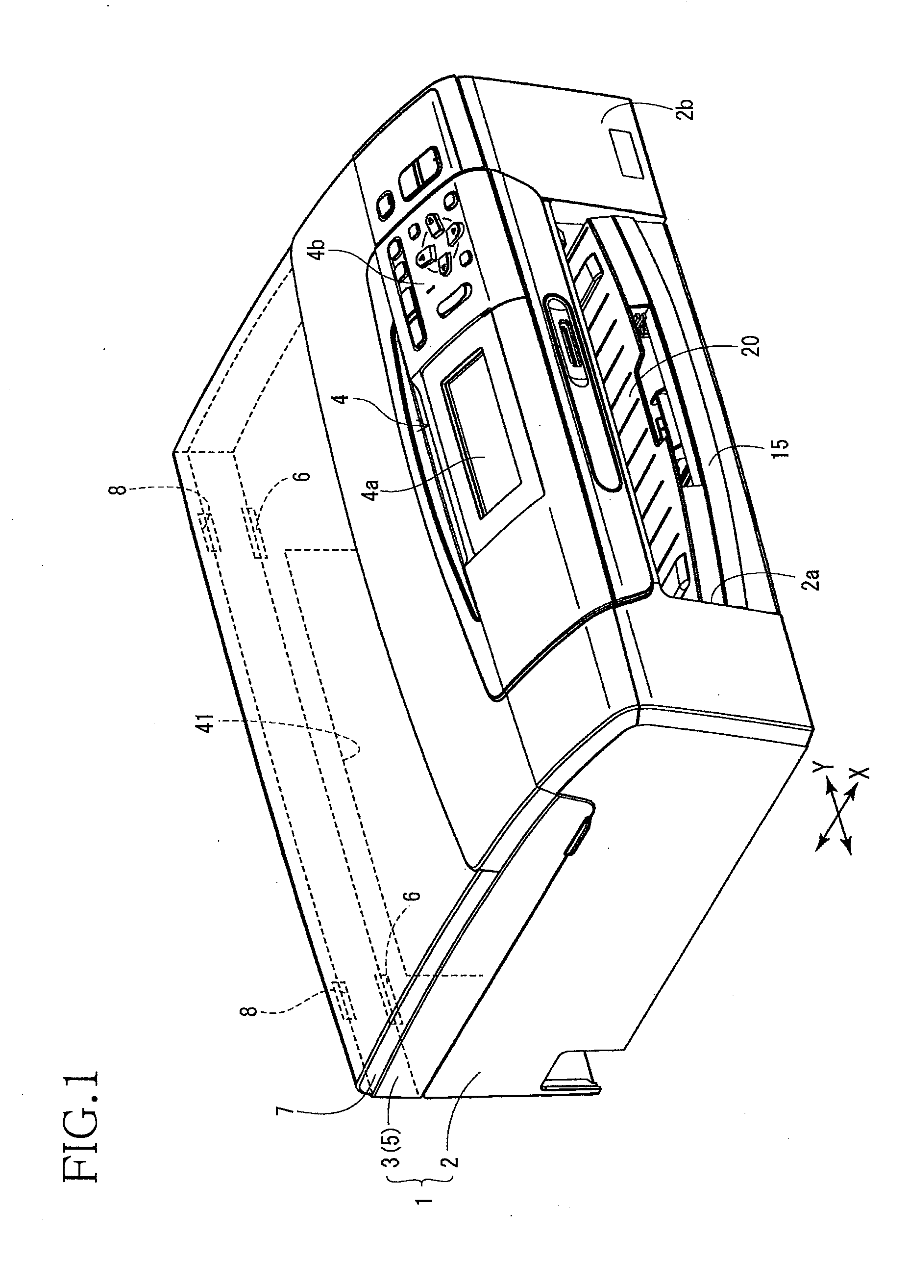
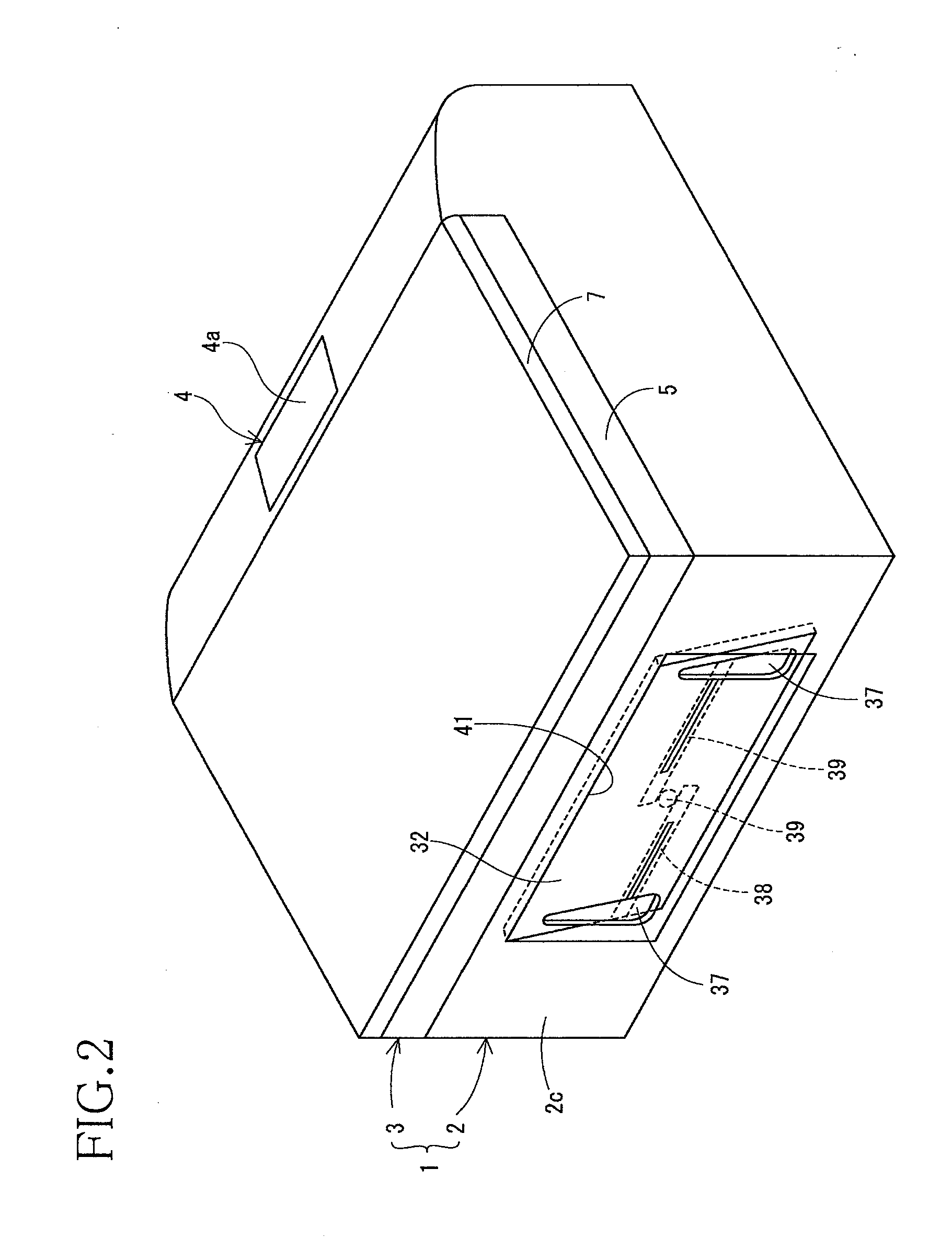
[0030]Referring first to FIGS. 1-3, there is shown an image recording apparatus 1 according to this invention in the form of a multi-function device (MFD) having a recording or printing function, a copying function, a scanning or image reading function and a facsimile transmission-reception function. As shown in the perspective views of FIGS. 1 and 2, the image recording apparatus 1 has a main body housing 2 which is an injection molding of a synthetic resin.

[0031]On the top surface of the main body housing 2, an upper unit 3 which is also an injection molding of a synthetic resin is connected to a rear end portion of the main body housing 2 pivotally about a second hinge portion 6, such that the upper unit 3 can be manually opened and closed relative to the top surface of the main body housing 2 in the vertical direction, that is, pivotable about the horizontally extending pivot axis of the second hinge portion 6. The main body housing 2 has a front opening 2a formed in its front s...

second embodiment

[0048]Referring next to FIGS. 4, 5A, 5B and 6, an image recording apparatus constructed according to this invention will be described. This image recording apparatus is configured to record an image on a surface of a third recording medium in the form of an optical disk 46 such as a CD-R or a DVD manually placed in a second manual medium insertion tray 45. The image may be a label identifying the optical disk 45, for example.

[0049]The second manual medium insertion tray 45 shown in the schematic perspective view of FIG. 4 is formed of a synthetic resin, and has a circular recess 47 formed in its upper surface such that the circular recess 47 has a diameter substantially equal to the diameter of the optical disk 46, so that the third recording medium in the form of the optical disk 46 can be manually set in the circular hole 47. The tray 45 further has a center boss 46a formed in the center of the circular recess 47 such that the center boss 46a has a height equal to the depth of the...

fifth embodiment

[0058]Referring to FIGS. 8-11, an image recording apparatus constructed according to this invention will be described.

[0059]As shown in FIG. 8, the image recording apparatus of the fifth embodiment is provided with a first manual medium insertion tray 50 including a sheet support plate 51 connecting the pair of arms 31, and a gate member 52 pivotally connected to the sheet support plate 51. The side guide device 33 described above with respect to the preceding embodiments is slidably disposed on the sheet support plate 51, and the gate member 52 is disposed between the two abutting plates 37 of the side guide device 33.

[0060]As shown in FIGS. 9-11, the gate member 52 is located between the sheet support plate 51 and the first hinge portion 34. The second recording medium is placed on the sheet support plate 51 and the gate member 52 while the first manual medium insertion tray 50 is placed in its operative position (indicated by solid line in FIG. 11) in which the sheet support plat...


PUM


Abstract

Image recording apparatus including manual medium insertion tray manually loaded with recording medium, the tray being connected to rear end portion of housing such that the tray is pivotable in vertical direction about horizontal axis of first hinge portion located below first hinge portion provided for image reading device, between its operative position in which the second recording medium is fed to feeding path leading to image recording device, and its retracted position, the tray placed in the operative position having upwardly inclined posture extending outwardly from the rear end portion of the housing, while the tray placed in the retracted position having posture extending generally downwards into accommodating space formed within the housing and on rear side of U-turn sheet transfer path connecting the sheet supply cassette and the feeding path, the tray being pivotable between the operative and retracted positions through rear opening formed in the housing.

Description

CROSS REFERENCE TO RELATED APPLICATION[0001]The present application claims the priority from Japanese Patent Applications Nos. 2010-056976 and 057041 both filed Mar. 15, 2010, the disclosure of which is herein incorporated by reference in its entirety.BACKGROUND OF THE INVENTION[0002]1. Field of the Invention[0003]The present invention relates generally to an image recording apparatus capable of recording or printing characters and other image data on a plurality of kinds of recording media, and more particularly to such an image recording apparatus of the type provided with a manual medium insertion tray on a rear side of its main body housing.[0004]2. Description of Related Art[0005]There is known an image recording apparatus provided with a manual medium insertion tray disposed in its main body housing and constructed to be manually loaded with a recording medium such as paper sheets. This image recording apparatus is of a single-function type such as a printer, a copier and a fa...

Claims


Application Information

Patent Timeline
IPC IPC(8): B41J15/04
CPCB41J3/4073B41J13/009B41J13/0081
Inventor ASADA, TETSUONAKAKITA, SATORU
Owner BROTHER KOGYO KK
Why Eureka
Try Eureka