Piezoelectric fan and cooling device

a piezoelectric fan and cooling device technology, applied in the direction of positive displacement liquid engine, piston pump, semiconductor/solid-state device details, etc., can solve the problems of affecting the air-moving performance of the piezoelectric fan, affecting the accuracy of positioning, and limiting the precision of positioning, so as to achieve the effect of improving the overall size of the cooling device, improving the air-moving performance of the vibrating plate and significantly increasing the cooling performan

Inactive Publication Date: 2011-09-15
MURATA MFG CO LTD
View PDF11 Cites 8 Cited by
  • Summary
  • Abstract
  • Description
  • Claims
  • Application Information

AI Technical Summary

Benefits of technology

[0014]To overcome the problems described above, preferred embodiments of the present invention provide a piezoelectric fan with which the air-moving performance of a vibrating plate is increased and thereby the cooling performance is improved, and also provide a cooling device including the piezoelectric fan.
[0017]Because the reinforcing member is preferably arranged at the position described above, the rigidity of a portion of the vibrating plate corresponding to the gap between the piezoelectric element and the fixing member is increased, and the following phenomenon occurs. That is, the reinforcing member prevents vibration of the portion of the vibrating plate corresponding to the gap G, and prevents a portion of vibration energy that is generated by expansion and contraction of the piezoelectric element from being consumed in the portion corresponding to the gap G, and thereby the amplitude of the vibration of the free ends of the vibrating plate is significantly increased. Thus, the air-moving performance of the piezoelectric fan is significantly increased.
[0018]Therefore, with the piezoelectric fan having this structure, the air-moving performance of the vibrating plate and the cooling performance are significantly increased.
[0027]In this case, the piezoelectric elements and the vibrating plate preferably define a bimorph vibrator. With this structure, the bending displacement relative to the applied voltage is increased and the amplitude of the vibration of the vibrating plate is increased. Therefore, the air-moving performance of the piezoelectric fan is further increased.
[0033]With this structure, the plurality of blades are bent toward the grooves between heat-dissipating fins. Therefore, a low profile cooling device is provided, so that the cooling performance can be increased without increasing the overall size of the cooling device.
[0034]With various preferred embodiments of the present invention, the air-moving performance of the vibrating plate and the cooling performance are significantly increased.

Problems solved by technology

Therefore, dissipation of heat generated in the apparatuses is an important issue.
In such circumstances, it has become an important issue to discharge warm air that is heated by a heat dissipater, such as a heatsink, which is disposed on an upper surface of the CPU, from the vicinity of the heat dissipater so as to prevent an increase in the temperature of the CPU.
This is because there is a limitation on the precision of positioning or because there are microscopic asperities on the surface of the fixing plate 13.
That is, the gap G impairs the air-moving performance of the piezoelectric fan 10.

Method used


Image

  • Piezoelectric fan and cooling device
  • Piezoelectric fan and cooling device
  • Piezoelectric fan and cooling device

Examples


first preferred embodiment

[0053]Hereinafter, a piezoelectric fan according to a first preferred embodiment of the present invention will be described.

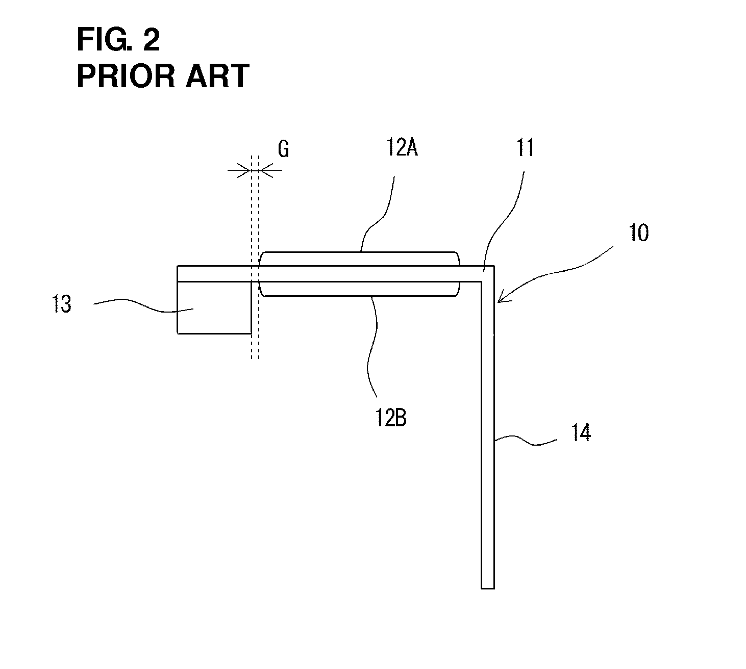
[0054]FIG. 4 is a perspective view of a piezoelectric fan 101 according to the first preferred embodiment, and FIG. 5 is a side view of the piezoelectric fan 101. FIGS. 6A and 6B are perspective views of a cooling device 1 including the piezoelectric fan 101. In FIG. 5, a vibrating plate is seen in side view in a direction in which the boundary between piezoelectric elements and a fixing member is visible. A gap G is illustrated in a slightly enlarged scale for convenience of illustration.

[0055]The piezoelectric fan 101 include a vibrating plate 111, piezoelectric elements 112A and 112B, a fixing plate 113, and reinforcing plates 151 and 152. A heatsink 20 preferably includes heat-dissipating fins 22 that extend upward from the base portion 21 so as to be parallel to each other. In FIGS. 6A and 6B, a heat-generating member 50 (heat-generating component), such a...

second preferred embodiment

[0070]FIG. 8A is a top view of a fixing plate 213 of a piezoelectric fan 201 according to a second preferred embodiment of the present invention, FIG. 8B is a front view of the fixing plate 213, and FIG. 8C is a side view of the fixing plate 213. FIG. 9 is a top view of the piezoelectric fan 201 according to the second preferred embodiment. FIG. 10 is a side view of the piezoelectric fan 201. In FIG. 10, a vibrating plate is shown in a side view in a direction in which the boundary between piezoelectric elements and a fixing member is visible.

[0071]The piezoelectric fan 101 according to the first preferred embodiment includes the reinforcing plates 151 and 152 arranged to increase the rigidity of the portion of the vibrating plate 111 corresponding to the gap G. The piezoelectric fan 201 according to the second preferred embodiment includes the fixing plate 213 preferably made of glass epoxy, for example, which is illustrated in FIGS. 8A to 8C. The fixing plate 213 preferably includ...

third preferred embodiment

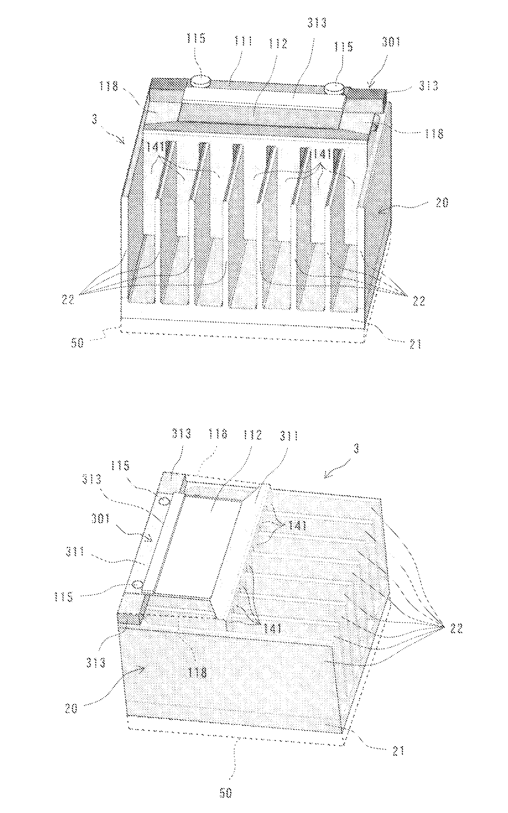
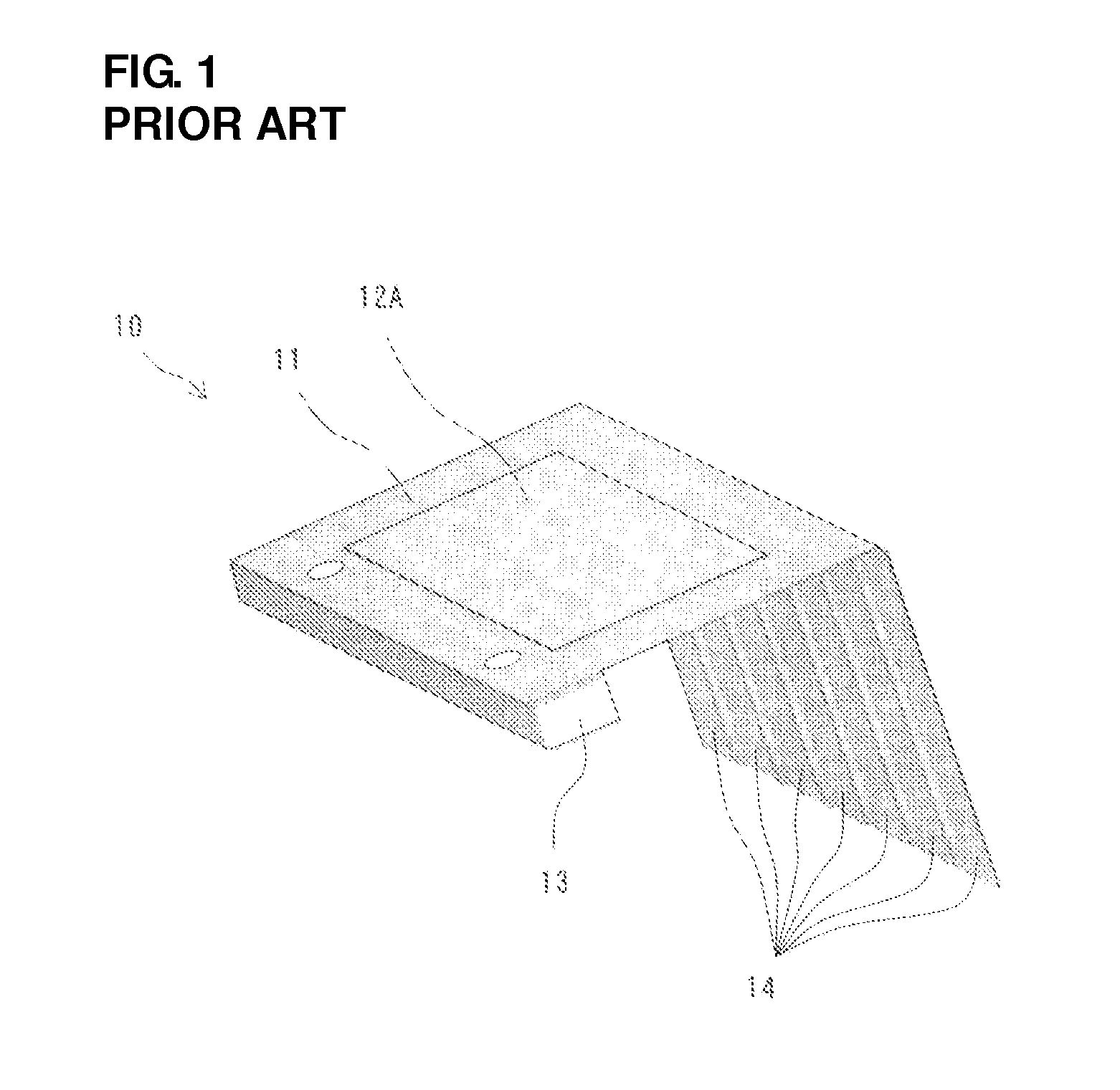
[0078]FIG. 11 is a perspective view of a piezoelectric fan 30, which is a modification of the piezoelectric fan 10 described in Kaneko. FIG. 12 is a perspective view of a piezoelectric fan 301 according to a third preferred embodiment of the present invention. FIG. 13 is a side view of the piezoelectric fan 301 according to the third preferred embodiment. FIGS. 14A and 14B are perspective views of a cooling device 3 including the piezoelectric fan 301 according to the third preferred embodiment. In FIG. 13, a vibrating plate is shown in side view in a direction in which the boundary between piezoelectric elements and a fixing member is visible.

[0079]First, in order to compare the air-moving performance of the piezoelectric fan 301 of the third preferred embodiment with the air-moving performance of the piezoelectric fan 30, which is a modification of the piezoelectric fan 10, the structure of the piezoelectric fan 30 will be described.

[0080]The piezoelectric fan 30 differs from the ...


PUM


Abstract

A piezoelectric fan includes reinforcing plates that increase the rigidity of a portion of the vibrating plate corresponding to a gap between a piezoelectric element and a fixing plate. First ends of the reinforcing plates are attached to portions of the vibrating plate on both sides of piezoelectric elements in the width direction, and second ends of the reinforcing plates are attached to a fixed end of the vibrating plate such that the second ends and the fixing plate sandwich the fixed end of the vibrating plate therebetween and such that the reinforcing plates extend over the gap. The reinforcing plates prevent vibration of the portion of the vibrating plate corresponding to the gap, prevent a portion of vibration energy generated by expansion and contraction of the piezoelectric elements from being consumed in the portion corresponding to the gap, and increase the amplitude of the vibration of blade ends.

Description

BACKGROUND OF THE INVENTION[0001]1. Field of the Invention[0002]The present invention relates to a piezoelectric fan that discharges warm air from the vicinity of a heat dissipater, and to a cooling device including the piezoelectric fan.[0003]2. Description of the Related Art[0004]Electronic components are mounted with high density in small electronic apparatuses. Therefore, dissipation of heat generated in the apparatuses is an important issue. For example, while the size of personal computers has decreased, the CPU clock rate has increased in order to improve the processing performance. As a result, in such an electronic apparatus, the airflow is reduced due to the high-density mounting of components while the amount of heat generated by the CPU, which is an example of a heat-generating member, has been increased. In such circumstances, it has become an important issue to discharge warm air that is heated by a heat dissipater, such as a heatsink, which is disposed on an upper sur...

Claims


Application Information

Patent Timeline
Patent Type & Authority Applications(United States)
IPC IPC(8): F04B35/04
CPCF04F7/00H01L23/3672H01L23/467H01L41/094H01L2924/0002H01L2924/00H10N30/2042
Inventor TANAKA, NOBUHIRAWADA, HIROAKI
Owner MURATA MFG CO LTD
Why Eureka
Try Eureka