Polarized Optics for Optical Diagnostic Device

a technology of optical diagnostic devices and polarized optics, applied in the field of clinical chemistry, can solve the problems of large opportunity and imprecise measuremen

Inactive Publication Date: 2011-09-15
SIEMENS HEALTHCARE DIAGNOSTICS INC
View PDF16 Cites 30 Cited by
  • Summary
  • Abstract
  • Description
  • Claims
  • Application Information

AI Technical Summary

Benefits of technology

[0012]An aspect of the present invention includes a readhead for a photometric diagnostic instrument, for illuminating a target area and detecting color information from the target area. The readhead includes a holder configured for receiving reagent sample media therein, the sample media having a plurality of test areas disposed in spaced relation thereon, each of the test areas configured to react with a sample when disposed in contact with the sample and to change color according to an amount of an analyte in the sample. One or more light sources are configured to emit light onto the test areas. One or more first polarized light filters having a first polarization direction are disposed optically between the light sources and the test areas, so that light reaching the test areas from the light sources is polarized in the first polarization direction. One or more light detectors are disposed to receive light reflected from the test areas. One or more second polarized light filters having a second polarization direction are disposed optically between the test areas and the light detectors. The first and second light filters are configured to enable said light detectors to receive diffuse, non-specular reflections of the light from the test areas when the sample media is indexed within said holder. The first and second light filters are also configured to substantially prevent said light detectors from receiving specular reflections of the light.

Problems solved by technology

Color comparisons made with the naked eye can lead to imprecise measurement.
A drawback of using this relatively large field of view, is that there is also a relatively great degree of opportunity for specular reflections from the light source to enter the field of view and obscure the image of the pad.

Method used


Image

  • Polarized Optics for Optical Diagnostic Device
  • Polarized Optics for Optical Diagnostic Device
  • Polarized Optics for Optical Diagnostic Device

Examples


example

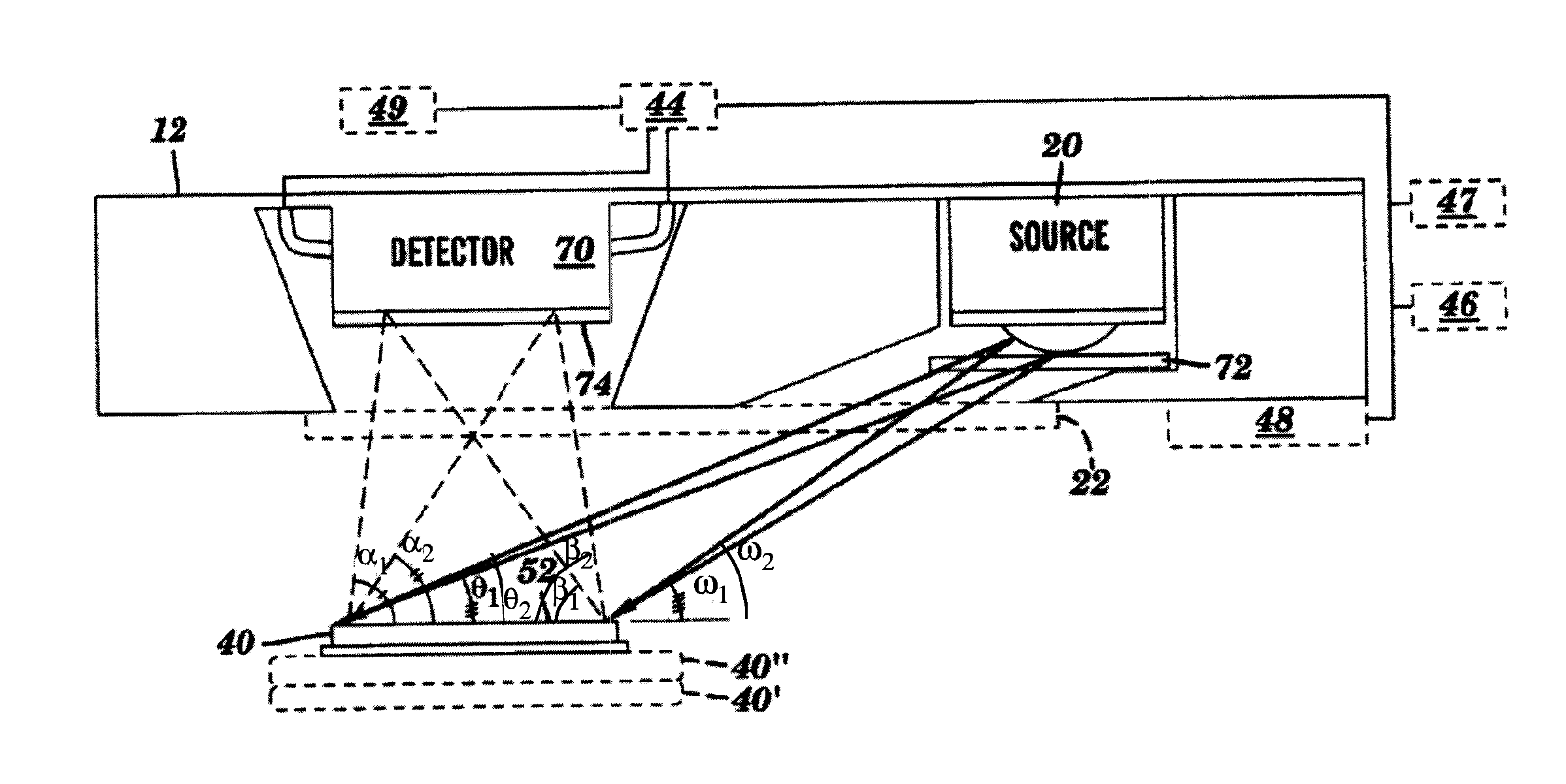
[0076]A readhead 12 was fabricated substantially as shown and described hereinabove with respect to FIGS. 1-4. Sample media substantially similar to a MULTISTIX® (Siemens) test strip 40 was tested with a broad range of analytes, using cross-polarized filters 72, 74 as shown. These test results were compared with the results of similar testing using parallel filters, and with results of similar testing on a commercial instrument which does not use polarization filters 72, 74. The commercial instrument used an optical read head described in U.S. Pat. Nos. 5,661,563 and 6,180,409. As shown in the following Table 11, the cross-polarized filters 72, 74 provided reflectances having a predominantly higher signal to noise ratio (S / N) than either of the other two configurations.

[0077]As shown in Table II, data from the perpendicular and parallel arrangements of polarization filters serve to compare the effect of orientations on reduction of specular reflections. It is understood that specula...


PUM

PropertyMeasurementUnit
timeaaaaaaaaaa
timeaaaaaaaaaa
timeaaaaaaaaaa

Abstract

A readhead for a photometric diagnostic instrument includes a holder configured for receiving reagent sample media therein. The sample media has a plurality of test areas configured to react with, and change color, according to an amount of an analyte in a sample. The holder is sized and shaped for forming an indexed fit with the sample media. One or more light sources are configured to emit light onto the test areas. First and second polarized light filters are respectively disposed between the light sources and the test areas, and between the test areas and one or more light detectors, so that the light detectors receive diffuse, non-specular reflections of the light from the test areas, while substantially preventing the light detectors from receiving specular reflections of the light.

Description

BACKGROUND[0001]1. Technical Field[0002]The present invention generally relates to the field of clinical chemistry. More particularly, the present invention relates to a readhead for an optical diagnostic system that analyzes the color change associated with one or more test areas on sample media following contact thereof with a liquid specimen, such as urine or blood.[0003]2. Background Information[0004]Throughout this application, various patents are referred to by an identifying citation. The disclosures of the patents referenced in this application are hereby incorporated by reference into the present disclosure.[0005]Sample media such as reagent test strips are widely used in the field of clinical chemistry. A test strip usually has one or more test areas spaced along the length thereof, with each test area being capable of undergoing a color change in response to contact with a liquid specimen. The liquid specimen usually contains one or more constituents or properties of inte...

Claims


Application Information

Patent Timeline
Patent Type & Authority Applications(United States)
IPC IPC(8): G01N21/00
CPCG01N21/21G01N21/78G01N21/8483G01N2021/8488Y10T436/10
Inventor PROFITT, JAMES A.
Owner SIEMENS HEALTHCARE DIAGNOSTICS INC
Why Eureka
Try Eureka