Radio terminal, radio base station, channel signal forming method and channel signal receiving method

a radio base station and channel signal technology, applied in the direction of multiplex communication, information relaying among terminal devices, orthogonal multiplex, etc., to prevent the quality of downlink assignment control information from degrading

Active Publication Date: 2011-09-15
SUN PATENT TRUST
View PDF9 Cites 19 Cited by
  • Summary
  • Abstract
  • Description
  • Claims
  • Application Information

AI Technical Summary

Benefits of technology

[0033]The present invention provides radio terminal, radio base station, channel signal forming method, and channel signal receiving method to prevent the quality of downlink assignment control information from degrading.

Problems solved by technology

However, when a downlink transmission bandwidth of a base station is wide, a base station transmits many PDCCH signals at once, so that a terminal cannot reduce the number of times of blind detection much in its normal operation, and the increase of circuit scale causes a problem.

Method used


Image

  • Radio terminal, radio base station, channel signal forming method and channel signal receiving method
  • Radio terminal, radio base station, channel signal forming method and channel signal receiving method
  • Radio terminal, radio base station, channel signal forming method and channel signal receiving method

Examples


embodiment 1

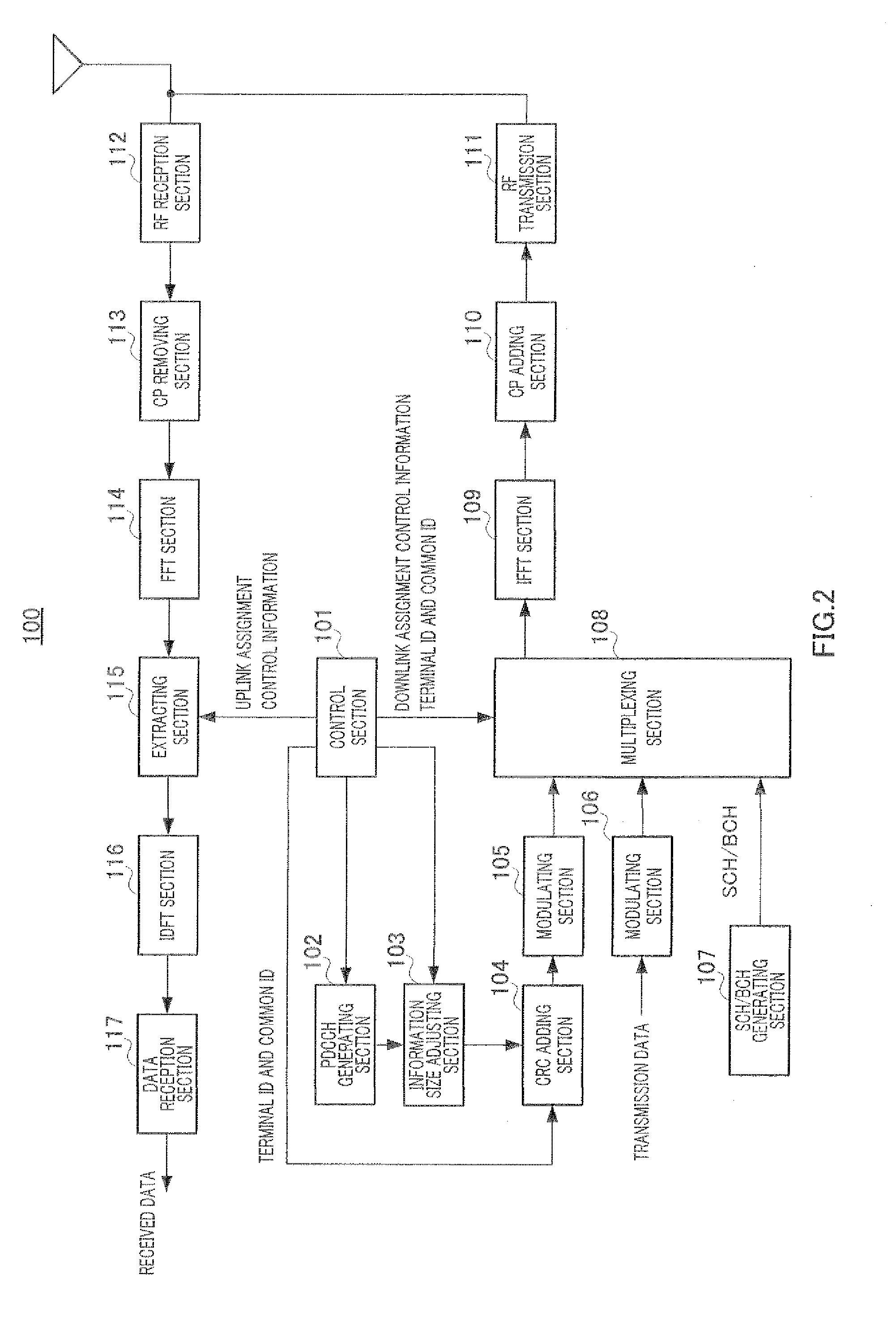
[0046]FIG. 2 is a block diagram showing a configuration of base station 100 according to Embodiment 1 of the present invention. In FIG. 2, base station 100 includes control section 101, PDCCH generating section 102, information size adjusting section 103, CRC (Cyclic Redundancy Check) adding section 104, modulating section 105 and 106, SCH / BCH generating section 107, multiplexing section 108, IFFT section 109, CP adding section 110, RF transmission section 111, RF reception section 112, CP removing section 113, FFT section 114, extracting section 115, IDFT section 116, and data reception section 117. Base station 100 is configured to be able to communicate with terminal 200 (described later) using a component band group composed of an uplink component band and a plurality of downlink component bands associated with the uplink component band. A component band group is set for each terminal 200. Some or all of a plurality of component bands composing the component band group allocated...

embodiment 2

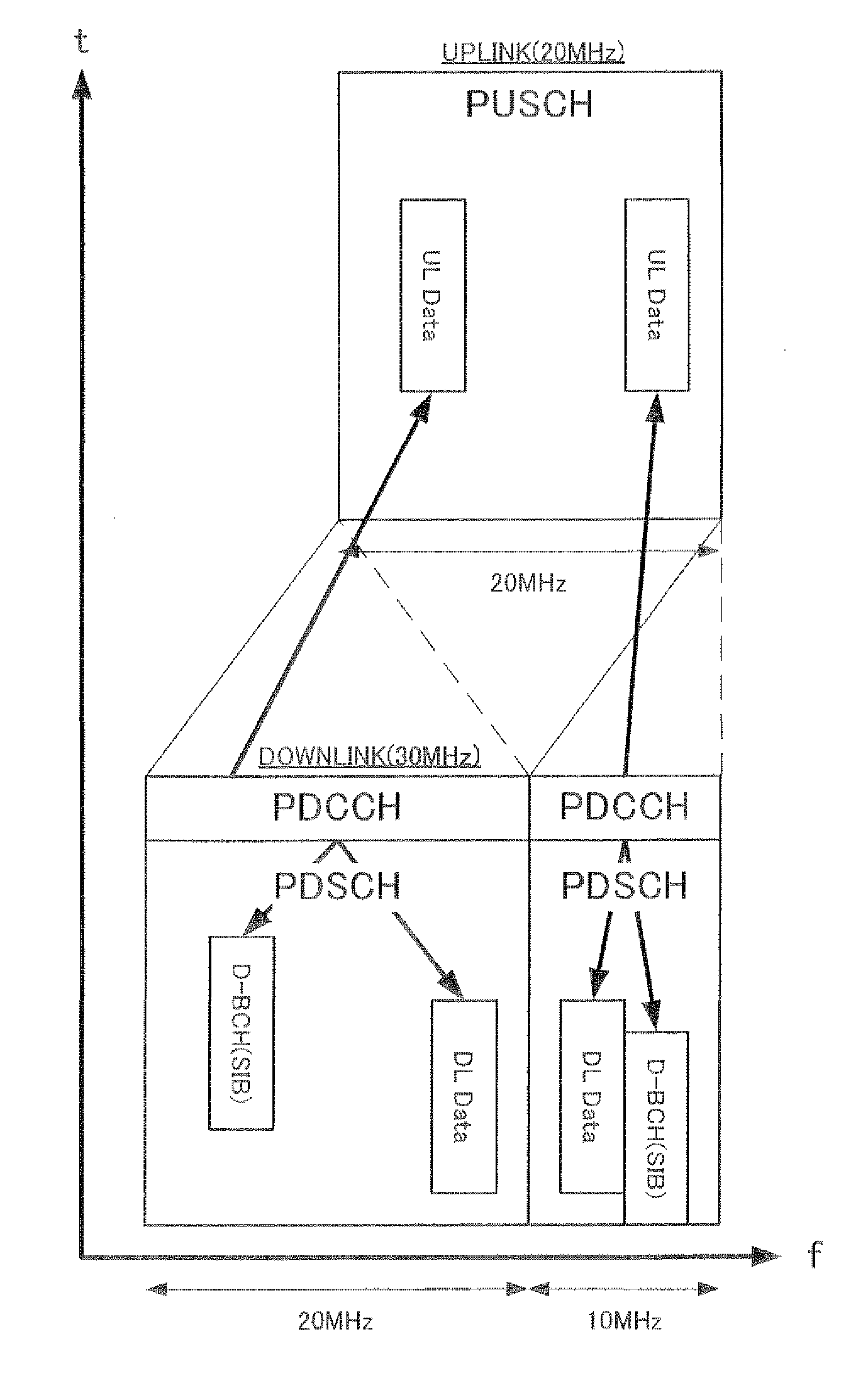
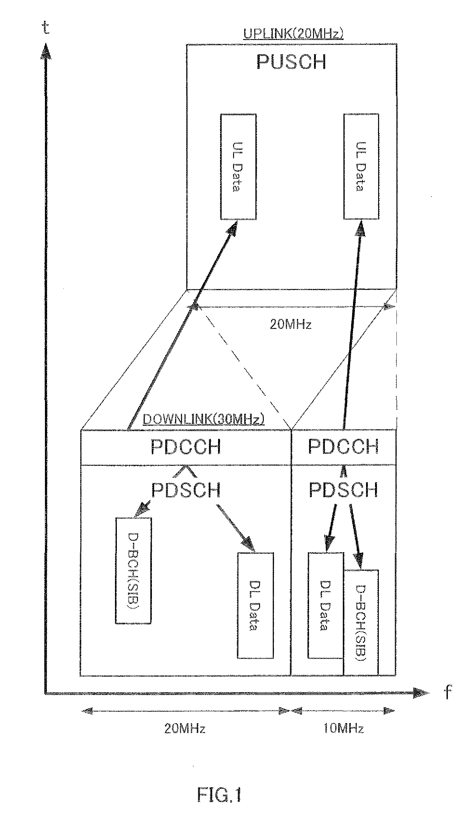
[0126]As Embodiment 1, the present embodiment explains the configuration, when the communication bandwidth (the number of basic component band) is asymmetric between an uplink and a downlink, in a common region, an LIE-A system specific broadcast information (D-BCH+) (that is, an LTE terminal does not need to receive) and broadcast information of an LTE system (D-BCH) are transmitted one after another by time division.

[0127]FIG. 9 is a block diagram showing the configuration of base station 300 of Embodiment 2 of the present invention. Compared to base station 100 of Embodiment 1 shown in FIG. 2, base station 300 shown in FIG. 9 adds BCH+ generating section 318 and includes control section 301 instead of control section 101, information size adjusting section 303 instead of information size adjusting section 103, and multiplexing section 308 instead of multiplexing section 108. Parts in FIG. 9 that are the same as in FIG. 2 will be assigned the same reference numerals as in FIG. 2 a...


PUM


Abstract

A radio terminal, radio base station, channel signal forming method and channel signal receiving method wherein when an upstream unit band and a plurality of downstream unit bands associated therewith are used to perform communications, the quality of downstream assignment control information can be prevented from being degraded. In a base station (100), the PDCCH signals including upstream assignment control information are limited to ones that are placed in some of the downstream unit bands. This can reduce the probability of performance of zero padding to downstream assignment control information having greater importance. Also in the base station (100), the PDCCH signals of the downstream unit bands other than the basic unit band include only downstream resource assignment information. For this reason, in the individual regions of the downstream unit bands other than the basic unit band, the bandwidth of the downstream unit bands is always used as a reference of size adjustment and hence requires no information size adjustment. As a result, there is no need of performing zero padding to the downstream assignment control information, so that the quality of downstream assignment control information can be prevented from being degraded.

Description

TECHNICAL FIELD[0001]The present invention relates to a radio terminal, radio base station, channel signal forming method and channel signal receiving method.BACKGROUND ART[0002]In 3GPP LTE, OFDMA (Orthogonal Frequency Division Multiple Access) is employed as a downlink communication method. In a radio communication system adopting 3GPP LTE, a base station transmits a synchronizing signal (synchronization channel: SCH) and a broadcast signal (broadcast channel: BCH) using prescribed communication resources. A terminal first synchronizes with a base station by capturing the SCH. Then, the terminal acquires parameters that are specific to that base station (for example, the frequency bandwidth) by reading BCH information (see Non-patent Literature 1, 2 and 3).[0003]Also, after the terminal acquires base station-specific parameters, the terminal sends a connection request to the base station, and, by this means, establishes communication with the base station. When necessary, the base ...

Claims


Application Information

Patent Timeline
Patent Type & Authority Applications(United States)
IPC IPC(8): H04W72/04
CPCH04L5/0053H04L5/001H04W72/042H04L5/0094H04L5/0044H04W72/23H04W88/08H04W72/53H04W72/21H04H20/08H04J11/00H04J11/0076H04L1/0038H04W72/0453H04W72/1273
Inventor NAKAO, SEIGOIMAMURA, DAICHIAOYAMA, TAKAHISA
Owner SUN PATENT TRUST
Why Eureka
Try Eureka