
Apparatus for high-frequency electromagnetic initiation of a combustion process

a combustion process and electromagnetic technology, applied in mechanical equipment, lighting and heating equipment, machines/engines, etc., can solve the problems of increased nox emissions, difficult burning, increased emissions,

Inactive Publication Date: 2011-09-22
GENERAL ELECTRIC CO
View PDF1 Cites 43 Cited by
  • Summary
  • Abstract
  • Description
  • Claims
  • Application Information

AI Technical Summary

Benefits of technology

[0008]Aspects and advantages of the invention will be set forth in part in the following description, or may be obvious from the description, or may be learned through practice of the invention.

Problems solved by technology

Higher burning temperatures, however, can lead to increased emissions, such as increased NOx emissions.
However, low BTU fuels can be difficult to burn and can also lead to increased NOx emissions.
Lower burning temperatures, however, can result in excessive carbon monoxide (CO) and unburned hydrocarbon (UHC) emissions due to incomplete fuel combustion that can result from lower burning temperatures.
Moreover, CO and UHC emissions can also result from operating a gas turbine at low load, such as during turndown conditions.
Existing systems for providing high-frequency electromagnetic radiation to the combustion zone of a combustor can require complex modifications to the existing structure of the combustor.
In addition, such systems often do not simultaneously provide electromagnetic radiation from a single source to multiple different regions of the gas turbine.
Moreover, existing systems may not provide the capability to focus the application of high-frequency electromagnetic radiation to low temperature regions of a combustor, such as proximate to unfired fuel nozzles for the combustor or to non-flame regions of the combustor.

Method used


Image

  • Apparatus for high-frequency electromagnetic initiation of a combustion process
  • Apparatus for high-frequency electromagnetic initiation of a combustion process
  • Apparatus for high-frequency electromagnetic initiation of a combustion process

Examples


Embodiment Construction

[0021]Reference now will be made in detail to embodiments of the invention, one or more examples of which are illustrated in the drawings. Each example is provided by way of explanation of the invention, not limitation of the invention. In fact, it will be apparent to those skilled in the art that various modifications and variations can be made in the present invention without departing from the scope or spirit of the invention. For instance, features illustrated or described as part of one embodiment can be used with another embodiment to yield a still further embodiment. Thus, it is intended that the present invention covers such modifications and variations as come within the scope of the appended claims and their equivalents.

[0022]In general, the present disclosure is directed to an apparatus and system for providing electromagnetic radiation to a combustor during a combustion process. While the present disclosure will be discussed with reference to a combustor used to generate...


PUM


Abstract

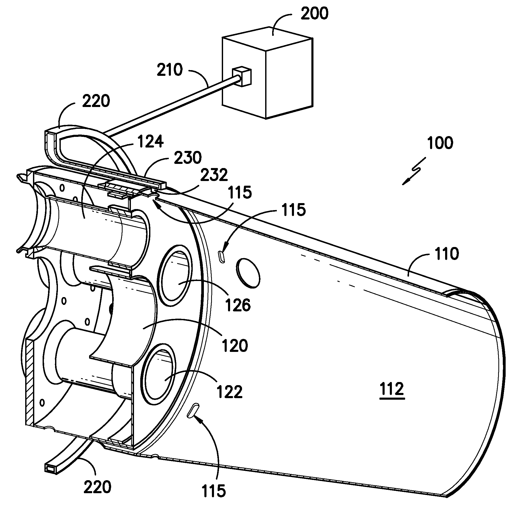
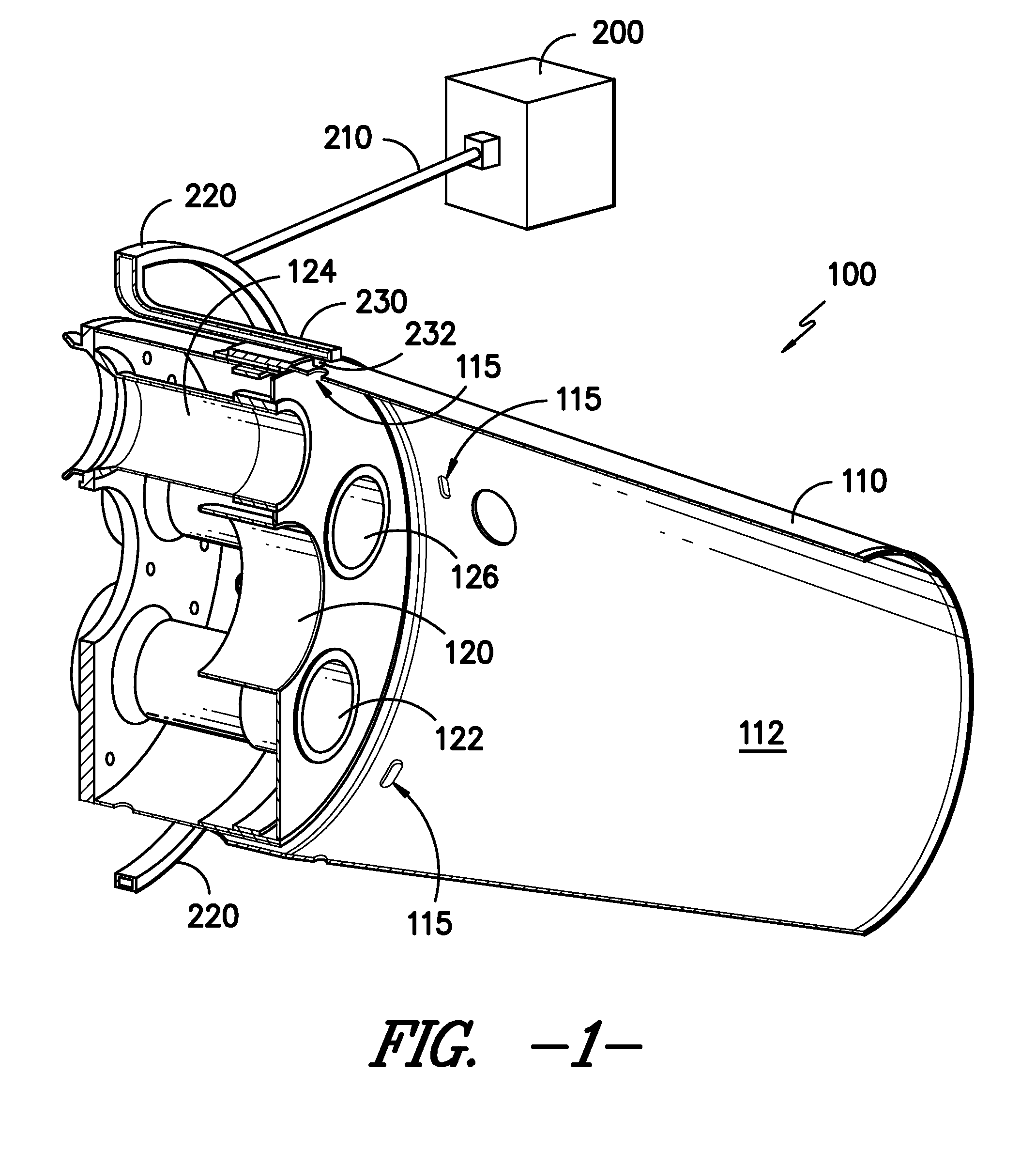
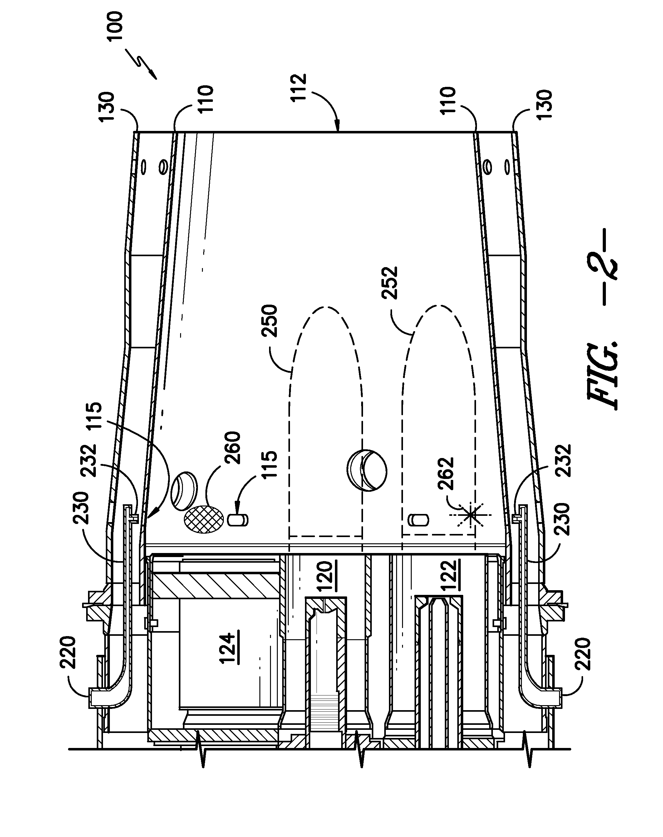
Apparatus for providing electromagnetic radiation to a combustor during a combustion process are disclosed. An electromagnetic radiation source delivers electromagnetic radiation through a first waveguide to a second waveguide that includes an electromagnetic radiation outlet positioned to deliver electromagnetic radiation to the interior of the combustor. Electromagnetic radiation is delivered to low temperature regions of a combustor to reduce carbon monoxide (CO) and unburned hydrocarbon (UHC) emissions. In addition, the electromagnetic radiation stimulates the combustion process so that lean air-fuel mixtures and low BTU gases can be burned at lower combustion temperatures leading to reduced NOx emissions.

Description

FIELD OF THE INVENTION[0001]The present disclosure relates generally to gas turbine combustors and, more particularly, to the use of high-frequency electromagnetic radiation during a combustion process in a combustor of a gas turbine.BACKGROUND OF THE INVENTION[0002]Gas turbines are widely used in commercial operations for power generation. A typical gas turbine includes a compressor at the front, one or more combustors around the middle, and a turbine at the rear. The compressor imparts kinetic energy to the working fluid (air) to bring it to a highly energized state. The compressed working fluid exits the compressor and flows to the combustors. The combustors mix fuel with the compressed working fluid, and the mixture of fuel and working fluid ignites to generate combustion gases having a high temperature, pressure, and velocity. The combustion gases flow to the turbine where they expand to produce work.[0003]Gas turbines are becoming increasingly required to perform at higher eff...

Claims


Application Information

Patent Timeline
IPC IPC(8): F02C7/264
CPCF23C99/001F23D2900/00014F23R2900/00002F23R3/286F23D2900/00015
Inventor VALEEV, ALMAZ KAMILEVICHOSKIN, SERGEY ADOLFOVICHMESHKOV, SERGEY ANATOLIEVICHMITROFANOV, VALERY ALEXANDROVICHTRETVAKOV, DMITRY VLADLENOVICH
Owner GENERAL ELECTRIC CO
Learn More