Control cable

Inactive Publication Date: 2011-09-22
CHUO SPRING
View PDF8 Cites 1 Cited by
  • Summary
  • Abstract
  • Description
  • Claims
  • Application Information

AI Technical Summary

Benefits of technology

[0008]The above control cable bonds the foam member to the outer circumferential surface of the outer cable by molding the foam member on the outer circumferential surface of the outer cable. Therefore, a degree of

Problems solved by technology

With such a control cable, a hammering noise is sometimes generated due to the control cable striking another member (such as the door panel or the floor panel).
However, since such a method involves producing the foam member by die cutting a sheet material, a restriction arises in shapes of the foam member that can be produced.
In addition, since the foam member must be bonded to the outer cable

Method used


Image

  • Control cable
  • Control cable
  • Control cable

Examples


Example

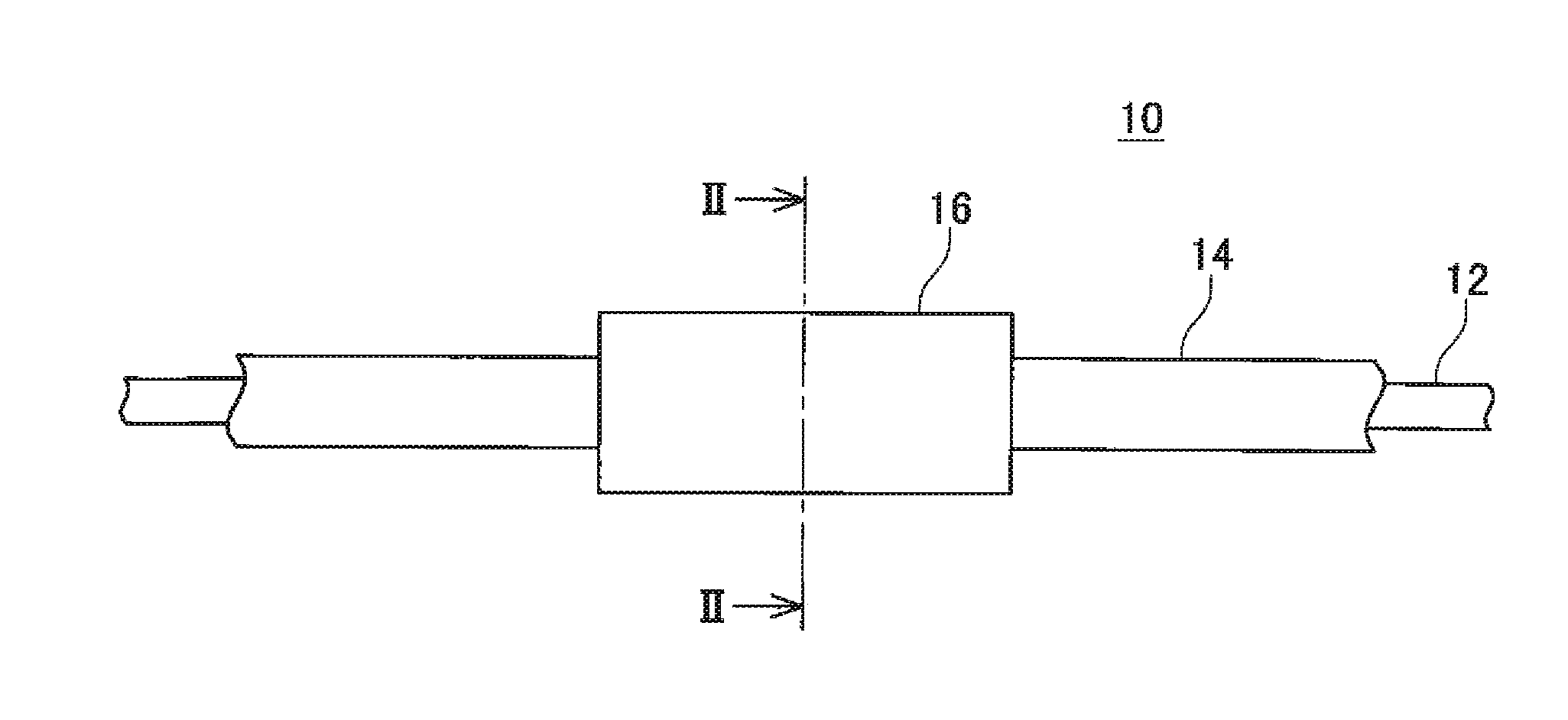
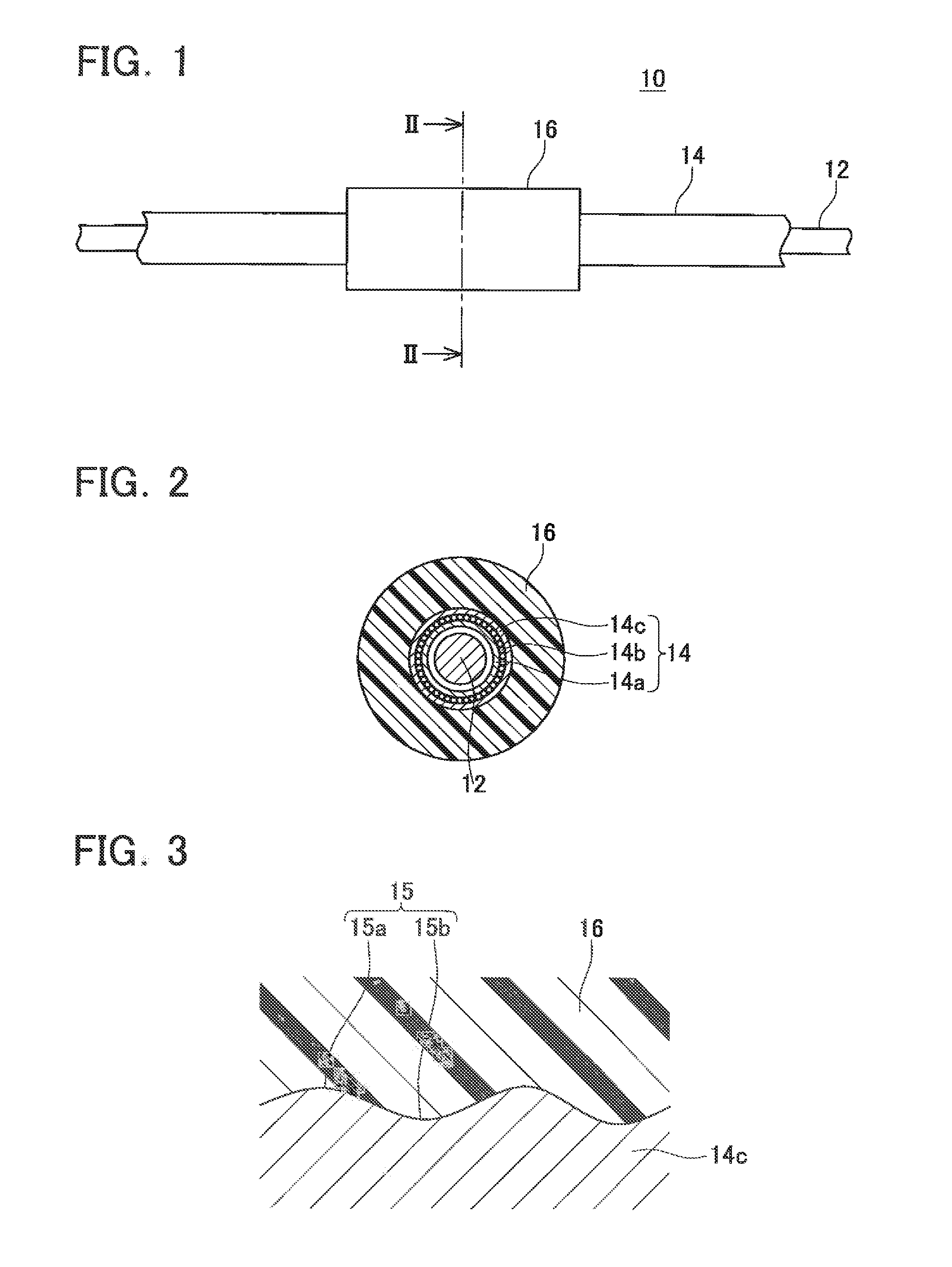
[0020]A control cable according to a representative embodiment of the present teachings will now be described. As shown in FIGS. 1 and 2, a control cable 10 comprises an inner cable 12, an outer cable 14 into which the inner cable 12 is slidably inserted, and a foam member 16 provided on an outer circumferential surface of the outer cable 14.

[0021]The inner cable 12 comprises a single metal wire. A hard steel wire, a stainless steel wire, an oil-tempered wire (e.g., SWO-A, SWO-B, or SWOSC-V), and a bluing wire may be used as a material of the inner cable 12. Zinc galvanizing may be applied on a surface of the inner cable 12. Mounting parts (not shown) may respectively be provided at both ends of the inner cable 12, whereby one end can be arranged so as to be mountable to an input device and the other end can be arranged so as to be mountable to an output device. Moreover, in addition to the configuration described above, various known configurations may be adopted for the inner cabl...


PUM


Abstract

A control cable 10 for an automotive application comprises an outer cable 14, an inner cable 12, and a foam member 16. The outer cable 14 includes an inner hollow. The inner cable 12 is slidably disposed within the inner hollow of the outer cable 14. The foam member 16 is bonded to an outer surface of the outer cable 14. The foam member 16 includes a foam material and is molded onto the outer surface of the outer cable 14.

Description

CROSS-REFERENCE TO RELATED APPLICATION[0001]This application claims priority to Japanese Patent Application No. 2010-62802, filed on Mar. 18, 2010, the contents of which are hereby incorporated by reference into the present application.TECHNICAL FIELD[0002]The present application generally relates to a control cable suitable for automotive applications, such as a control cable for locking and unlocking an automobile door, a hinged gas cap cover / lid, a reclining seat, an engine lid, or a trunk lid.DESCRIPTION OF RELATED ART[0003]In a vehicle (e.g., an automobile, a motorcycle, or an industrial vehicle such as a forklift), an input device and an output device may be disposed at positions separated from each other and input to the input device may be transferred to the output device via a control cable. Such a control cable includes an outer cable and an inner cable slidably inserted into the outer cable. Due to an advancing / retreating movement of the inner cable in the outer cable, th...

Claims


Application Information

Patent Timeline
IPC IPC(8): F16C1/10
CPCF16C1/108Y10T74/20402F16C1/26
Inventor HAYASHIDA, TAKAAKIMISAKI, YOSHIOMORI, NAOYUKI
Owner CHUO SPRING
Why Eureka
Try Eureka