Reduction of Greenhouse Gases

a technology of greenhouse gas and greenhouse gas, applied in the field of greenhouse gas reduction, can solve the problems of very limited methods of minimizing stacks, and achieve the effects of reducing greenhouse gas emissions, reducing waste heat to the receiving stream, and reducing greenhouse emissions

Inactive Publication Date: 2011-09-22
RAGSDALE RALPH DENVER
View PDF7 Cites 0 Cited by
  • Summary
  • Abstract
  • Description
  • Claims
  • Application Information

AI Technical Summary

Benefits of technology

[0012]The key to the new process is the continuous transfer of heat from the nuclear reaction to the facility requiring heat for its operation, by utilizing one or more circulating fluid loops between the two otherwise separate facilities. Depending on the degree of utilization, greenhouse gases emissions may be reduced from a minor extent to virtually obviating the need to operate fired pro...

Problems solved by technology

However, such methods of mi...

Method used


Image

  • Reduction of Greenhouse Gases
  • Reduction of Greenhouse Gases
  • Reduction of Greenhouse Gases

Examples


Embodiment Construction

Brief Description of Drawings

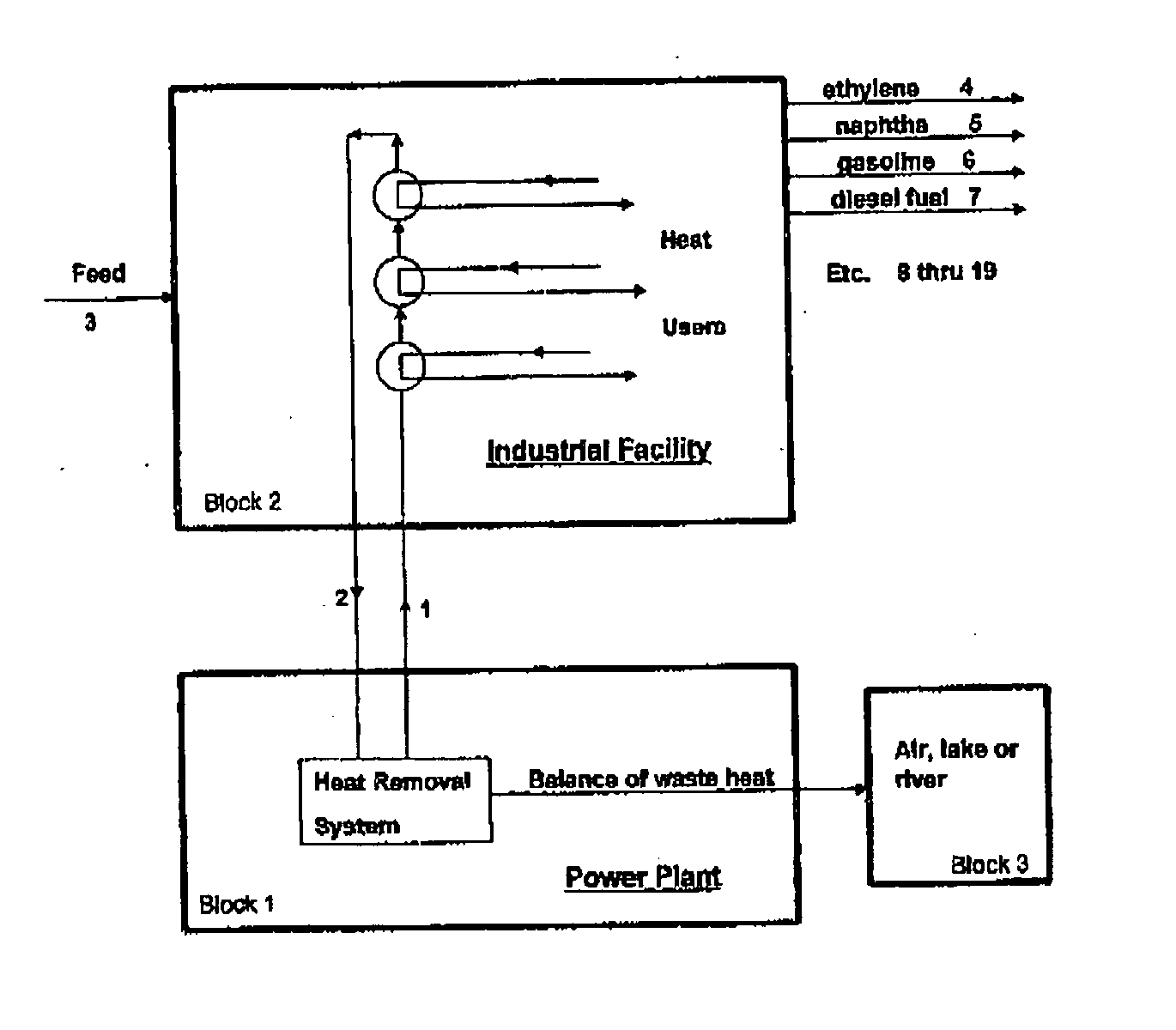
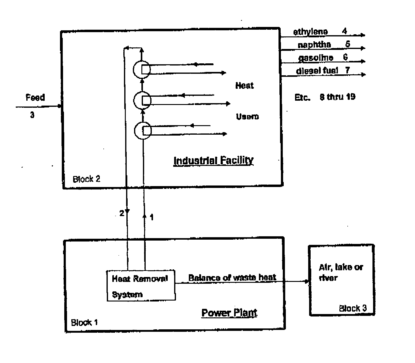
[0015]FIG. 1 is a schematic of the base processing scheme and also Alternate No. 1 processing scheme.

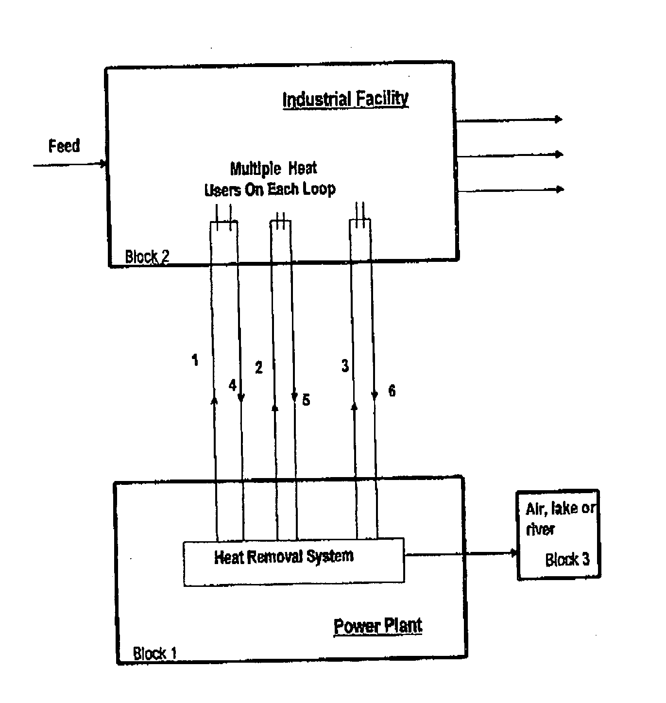
[0016]FIG. 2 is a schematic of Alternate No. 2 processing scheme.

[0017]FIG. 3 is a schematic of Alternate No. 4 processing scheme.

DETAILED DESCRIPTION

[0018]The base processing scheme is depicted in drawing FIG. 1. Heat from a nuclear electric power plant (block 1) is diverted from some power generation and from the receiving lake or river (block 3) by material flowing hot to the industrial plant that requires the heat (block 2) through piping [1], and returning cooled in piping [2]. The flowing fluid is organic or inorganic vapor, liquid, molten fluid or slurry as required by the processes employed in the industrial plant, with necessary modifications to conventional reactor heat removal facilities in the nuclear plant design.

[0019]Using a petroleum refinery as an example, the amount of heat removed from the circulating hot fluid loop depends on the crude...


PUM


Abstract

The heat removal and recovery systems of a nuclear energy source and the heat requirements of a nearby industrial facility are designed to achieve zero or near-zero greenhouse gas emissions from the industrial facility. Alternative arrangements of heat loops or belts to and from the nuclear heat source and within the industrial facility utilize heat exchange equipment at the interfaces and replace the use of fired furnaces and boilers. Technologies and processes can be selected to avoid the need or use of all or most of the furnaces and boilers. The design scheme applies to both new and existing retrofitted industrial facilities.

Description

CROSS-REFERENCES TO RELATED APPLICATIONS[0001]Not ApplicableSTATEMENT REGARDING FEDERALLY SPONSORED RESEARCH OR DEVELOPMENT[0002]Not ApplicableTHE NAMES OF THE PARTIES TO A JOINT RESEARCH AGREEMENT[0003]Not ApplicableINCORPORATION-BY-REFERENCE OF MATERIAL SUBMITTED ON A COMPACT DISC[0004]Not ApplicableBACKGROUND OF THE INVENTION[0005]1. Technical Field[0006]This invention relates to methods of reducing greenhouse gases emissions from petroleum refineries, chemical plants, bitumen upgraders, and other industrial facilities. Many conventional processes within such facilities employ heaters, furnaces, and boilers wherein gas or oil is combusted, resulting in flue gases to the atmosphere. This invention obviates the need for such furnaces by utilizing heat from a nuclear reactor in a nearby nuclear power plant or a mini reactor within the industrial facility itself The field of nuclear reactor cooling is involved as well.[0007]2. Background Art[0008]Petroleum refineries designed and ope...

Claims


Application Information

Patent Timeline
IPC IPC(8): C10G19/00
CPCG21D9/00C10G2300/4056Y02E30/00Y02P30/00
Inventor RAGSDALE, RALPH DENVER
Owner RAGSDALE RALPH DENVER
Why Eureka
Try Eureka