Intake and injection device, system, and internal combustion engine

a technology for injection devices and internal combustion engines, applied in the direction of machines/engines, electric control, combustion air/fuel air treatment, etc., can solve the problems of affecting the risk of performance drop, and the inability to adapt the quantity of fuel, so as to improve the ignition and combustion of the air-fuel mixture, improve the smoothness of the engine, and reduce the emission of exhaust gas

Inactive Publication Date: 2014-05-01
ROBERT BOSCH GMBH
View PDF6 Cites 1 Cited by
  • Summary
  • Abstract
  • Description
  • Claims
  • Application Information

AI Technical Summary

Benefits of technology

[0003]The intake and injection device according to the present invention for an internal combustion engine, the system according to the present invention for the intake, injection, and ignition of fuel of an internal combustion engine, and the internal combustion engine according to the present invention has the advantage over the related art that the internal combustion engine is operable with improved engine smoothness and reduced exhaust gas emissions. The throttle valve of the intake and injection device according to the present invention is situated rotated by approximately 90° in relation to the throttle valve known from the related art, so that the rotational axis extends essentially in parallel to the intermediate plane. This has the advantage that the air stream suctioned in in the direction of the first and second inlet openings is allocated somewhat asymmetrically by a partially open throttle valve and is swirled more strongly. During the injection of the fuel through the injection device, better mixing of fuel and air therefore occurs, so that a more homogeneous air-fuel mixture is produced. In particular, the air stream is swirled in such a way that different air flows and preferably also different quantities of air are suctioned in in the direction of the first and second inlet openings. Increased mixing of the air-fuel mixture in the combustion chamber is achieved in this way. Such increased mixing improves the ignition and combustion of the air-fuel mixture in the combustion chamber, whereby the engine smoothness of the internal combustion engine is improved and flaws in the combustion process, misfiring, or incomplete combustion of the fuel mixture are prevented. In this way, a reduction of the crude exhaust gases is also achieved. In addition, the compatibility for exhaust gas remaining in the combustion chamber from the prior combustion is increased. Due to the crude exhaust gas reduction, the catalytic converter may advantageously be dimensioned smaller and some of the noble metals required for the catalytic converter may be saved. The improved combustion and the improved engine smoothness achieved in this way additionally allow a lower idle speed, which in turn reduces the greenhouse gas emissions. Furthermore, due to the optimized mixing of the air-fuel mixture in the combustion chamber, it is possible to drive in the part-load range with an elevated residual gas fraction, whereby the fuel consumption is reduced. The internal combustion engine preferably includes more than one cylinder, each of the cylinders including one combustion chamber, with each having two intake valves and one throttle valve pivotable around a rotational axis, the rotational axis extending essentially in parallel to an intermediate plane in each cylinder, the intermediate plane extending between the first and second inlet openings centrally through the intake manifold. The intake and injection device includes in particular a cylinder head of the internal combustion engine, the internal combustion engine being the internal combustion engine of a motorcycle in particular. The fuel injector system preferably injects fuel within the scope of an upstream injection or an intake-synchronized injection, the upstream injection particularly preferably being combined with optimized spray targeting. Reduced exhaust gas emissions in the cold start phase may be achieved in this way. In the case of intake-synchronized injection, increased filling and a reduced tendency to knock of the internal combustion engine in normal operation at full load are achieved (cooling of the fresh air charge in the combustion chamber due to lesser intake manifold and cylinder wall wetting).

Problems solved by technology

Since the injection procedure is already completed at this point in time, the quantity of the fuel may no longer be adapted to the greater quantity of air, so that the air-fuel mixture in the combustion chamber is made leaner and therefore the risk exists of a performance drop, and possibly even misfires.

Method used


Image

  • Intake and injection device, system, and internal combustion engine
  • Intake and injection device, system, and internal combustion engine
  • Intake and injection device, system, and internal combustion engine

Examples


Embodiment Construction

[0019]Identical parts are always provided with identical reference numerals in the various figures and are therefore also generally only cited or mentioned once in each case.

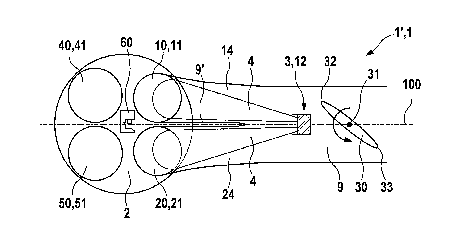
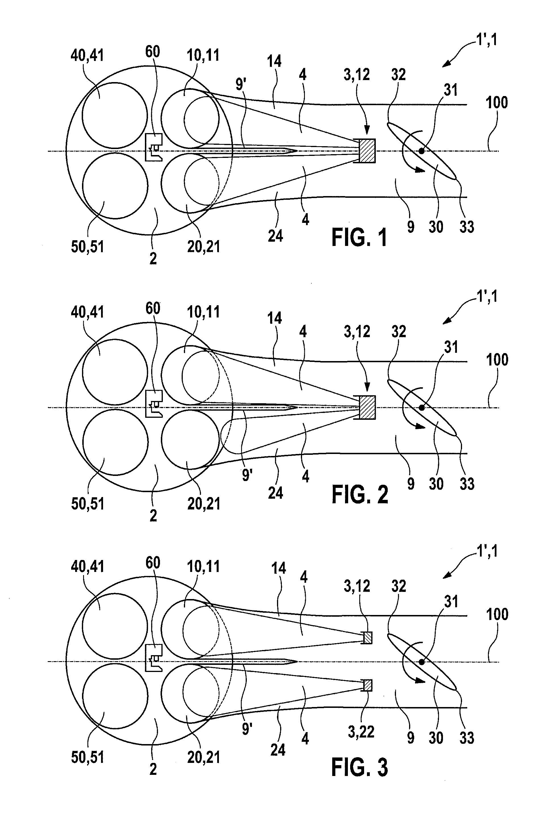
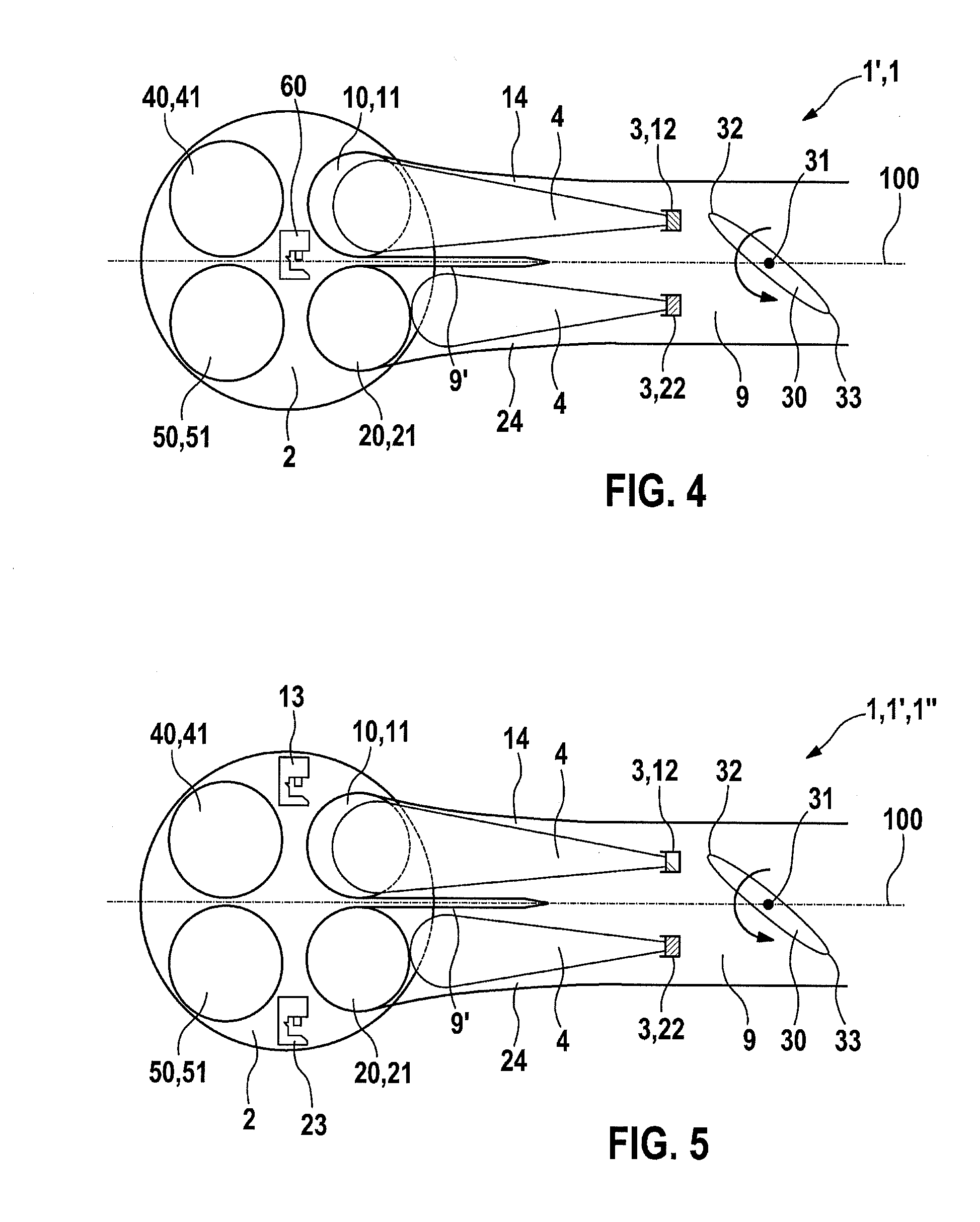
[0020]FIG. 1 shows a schematic view of an intake and injection device 1′ for an internal combustion engine 1 according to a first specific embodiment of the present invention. Internal combustion engine 1, which in the present example has only one cylinder, includes a combustion chamber 2, in which a piston 2′ moves. The wall of combustion chamber 2 has a first and a second inlet opening 10, 20, through each of which an air-fuel mixture is suctioned into combustion chamber 2, and a first and a second outlet opening 40, 50, through which the crude exhaust gases of the combusted air-fuel mixture are expelled from combustion chamber 2 into first and second outlet channels. Internal combustion engine 1 has a first intake valve 11, which is provided for closing first inlet opening 10 and is situated between a first c...


PUM


Abstract

An intake and injection device for an internal combustion engine, in particular of a motorcycle, is provided, having a fuel injector system, which is situated in an intake manifold leading to a combustion chamber of the internal combustion engine. The fuel injector system is designed for injecting fuel both in the direction of a first inlet opening and in the direction of a second inlet opening of the combustion chamber. The intake and injection device also has a throttle valve situated in the intake manifold, which is pivotable around a rotational axis. The intake and injection device is designed in such a way that the rotational axis extends essentially in parallel to an intermediate plane, which extends centrally through the intake manifold between the first and second inlet openings.

Description

FIELD OF THE INVENTION[0001]The present invention is directed to an intake and injection device for an internal combustion engine.BACKGROUND INFORMATION[0002]Devices for injecting and igniting fuel for internal combustion engines are generally known in principle. For example, an internal combustion engine having at least one combustion chamber is known from the publication German Published Patent Application No. 10 2008 044 244, the combustion chamber having two fuel inlet openings, which are each closable by an intake valve. The internal combustion engine also has a fuel injection device, which, assigned to the at least one combustion chamber, has a first fuel injector and a separate second fuel injector for the metered injection of fuel into at least one intake manifold of the combustion chamber. The fuel injectors inject the atomized fuel in the form of spray jets in the direction of the intake valves. Furthermore, a throttle valve is situated in the intake manifold, which is piv...

Claims


Application Information

Patent Timeline
Patent Type & Authority Applications(United States)
IPC IPC(8): F02M57/00
CPCF02M35/162F02M35/10216F02M57/00F02M35/1085F02P15/08F02M35/10177F02M69/044F02P15/02F02D41/3094
Inventor POSSELT, ANDREASLORENZ, MARKOGUTSCHER, ANDREAS
Owner ROBERT BOSCH GMBH
Why Eureka
Try Eureka