Systems and methods for deactivating a matrix converter

a matrix converter and deactivation method technology, applied in the direction of electric devices, battery/fuel cell control arrangement, transportation and packaging, etc., can solve the problems of reducing the overall efficiency of operation, transient voltage spike exceeding the breakdown voltage of a semiconductor device, and potentially damaging voltage spike across components of the matrix converter

Active Publication Date: 2011-09-22
GM GLOBAL TECH OPERATIONS LLC
View PDF46 Cites 39 Cited by
  • Summary
  • Abstract
  • Description
  • Claims
  • Application Information

AI Technical Summary

Problems solved by technology

However, abruptly stopping the current to / from a reactive component(s) may result in a potentially damaging voltage spike across components of the matrix converter caused by the potential energy stored by the reactive component(s).
For example, abruptly stopping the current flowing through an inductor may result in a transient voltage spike that exceeds the breakdown voltage of a semiconductor device.
Snubbers are additional lossy components that reduce the overall efficiency of operation.

Method used


Image

  • Systems and methods for deactivating a matrix converter
  • Systems and methods for deactivating a matrix converter
  • Systems and methods for deactivating a matrix converter

Examples


Embodiment Construction

following figures, wherein like reference numbers refer to similar elements throughout the figures.

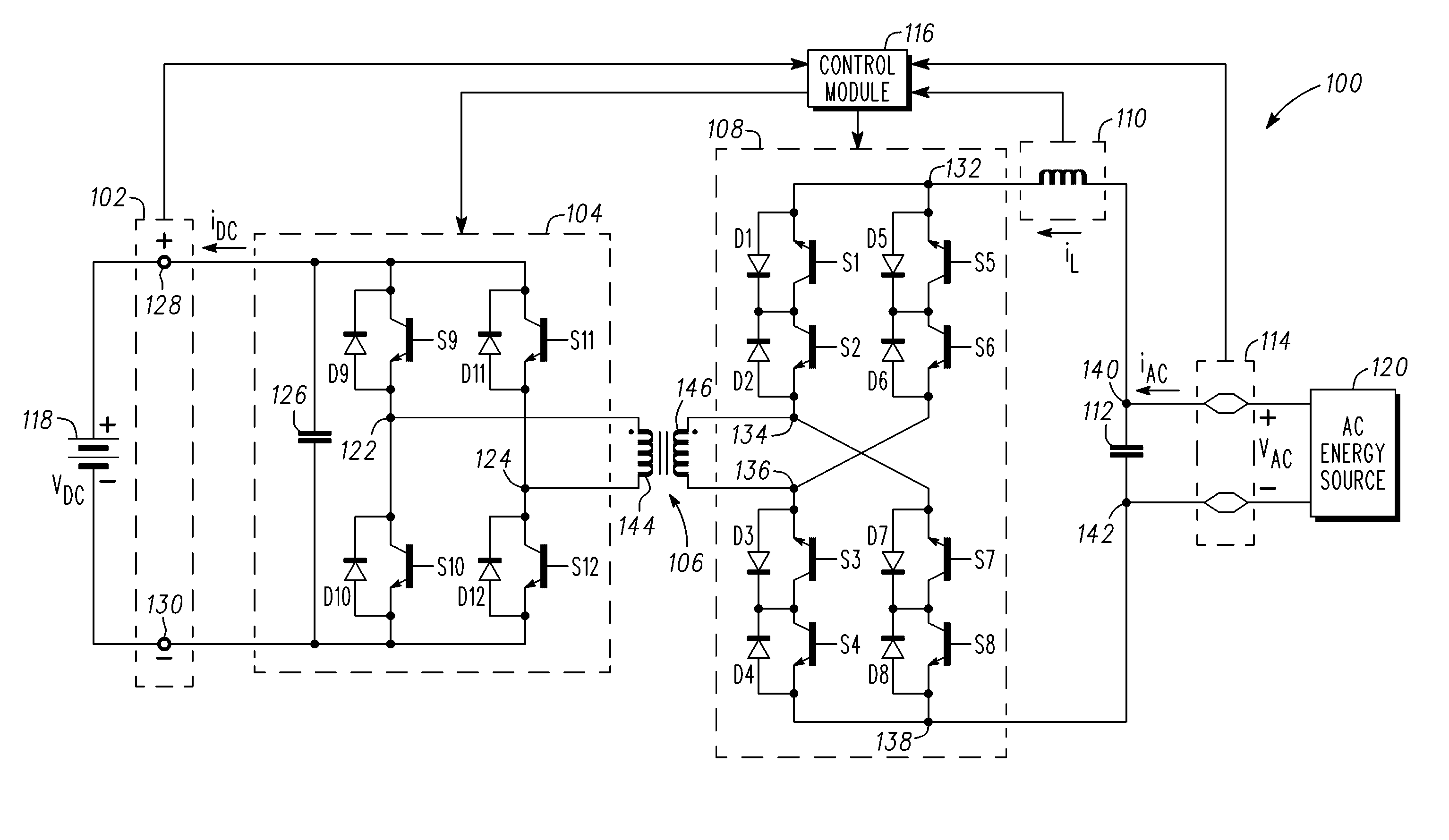
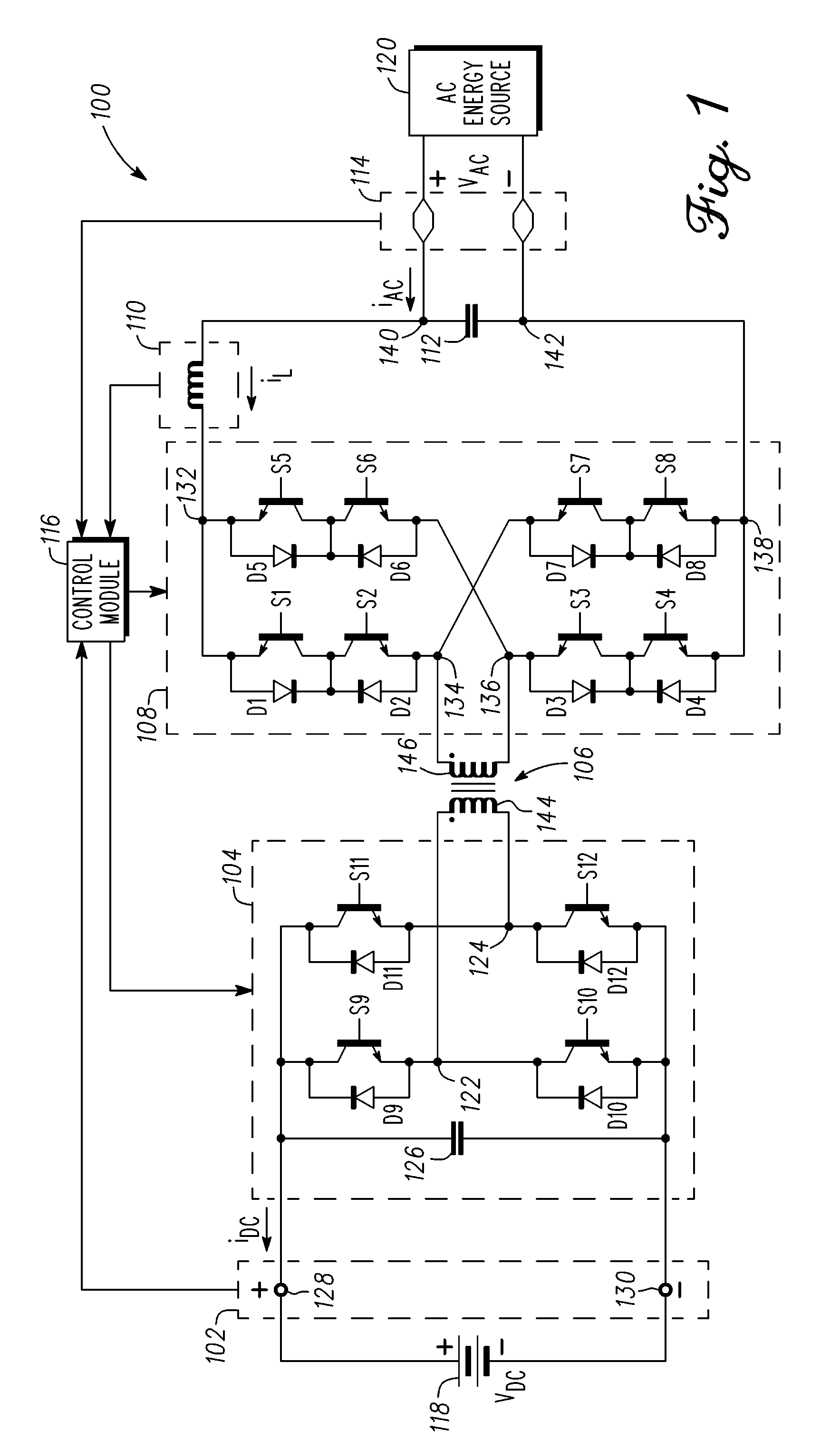
[0011]FIG. 1 is a schematic view of a electrical system suitable for use in a vehicle in accordance with one embodiment;

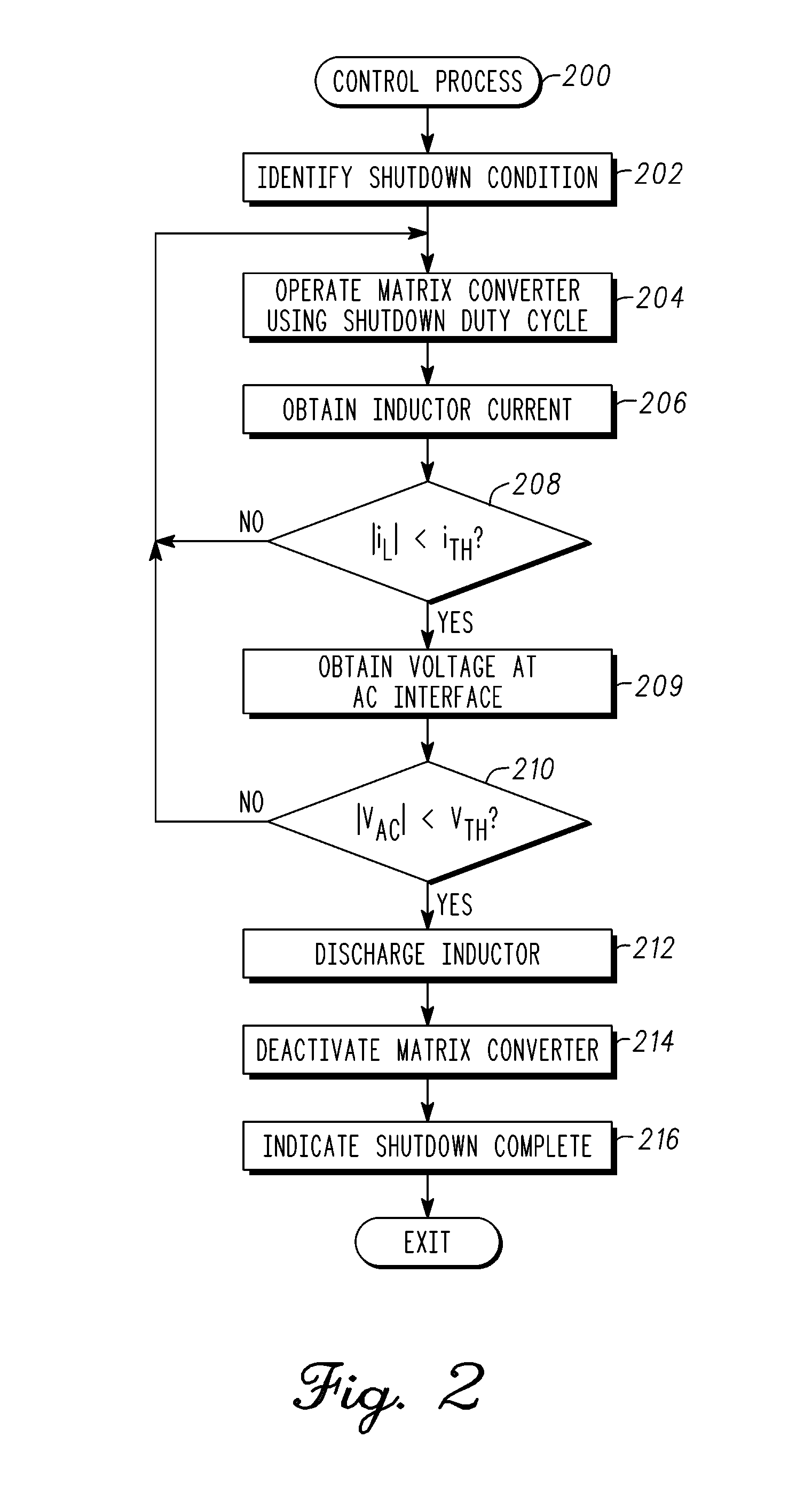
[0012]FIG. 2 is a flow diagram of control process suitable for use with the electrical system of FIG. 1 in accordance with one embodiment; and

[0013]FIG. 3 is a flow diagram of control process suitable for use with the electrical system of FIG. 1 in accordance with one embodiment.

DETAILED DESCRIPTION

[0014]The following detailed description is merely illustrative in nature and is not intended to limit the embodiments of the subject matter or the application and uses of such embodiments. As used herein, the word “exemplary” means “serving as an example, instance, or illustration.” Any implementation described herein as exemplary is not necessarily to be construed as preferred or advantageous over other implementations. Furthermore, there is no intention to be bound by an...


PUM


Abstract

Systems and methods are provided for deactivating a matrix conversion module. An electrical system comprises an alternating current (AC) interface, a matrix conversion module coupled to the AC interface, an inductive element coupled between the AC interface and the matrix conversion module, and a control module. The control module is coupled to the matrix conversion module, and in response to a shutdown condition, the control module is configured to operate the matrix conversion module to deactivate the first conversion module when a magnitude of a current through the inductive element is less than a threshold value.

Description

STATEMENT REGARDING FEDERALLY SPONSORED RESEARCH OR DEVELOPMENT[0001]This invention was made with Government support under Agreement No. DE-FC26-07NT43123, awarded by the United States Department of Energy. The Government has certain rights in this invention.TECHNICAL FIELD[0002]Embodiments of the subject matter described herein relate generally to electrical systems in automotive vehicles, and more particularly, embodiments of the subject matter relate to energy delivery systems with galvanic isolation.BACKGROUND[0003]Matrix converters (or cycloconverters) may be used in electric and / or hybrid vehicles to accommodate delivery of relatively high power over a relatively wide range of operating voltages, while at the same time achieving galvanic isolation, relatively high power factors, low harmonic distortion, relatively high power density and low cost. Matrix converters may be used to deliver energy from an alternating current (AC) energy source, such as the single-phase grid electr...

Claims


Application Information

Patent Timeline
Patent Type & Authority Applications(United States)
IPC IPC(8): B60L1/00H02M7/5387
CPCB60L3/00B60L11/1811H02M1/36Y02T90/14Y02T10/7005Y02T90/127H02M7/217Y02T10/7072B60L53/20B60L58/15Y02T10/70Y02T90/12
Inventor RANSOM, RAY M.
Owner GM GLOBAL TECH OPERATIONS LLC
Why Eureka
Try Eureka