Advanced matrix converter and method for operation

a matrix converter and converter technology, applied in the direction of power conversion systems, circuit arrangements, ac-ac conversion, etc., can solve the problems of heavy idg subsystems, inconvenient operation, and inability to directly supply power to frequency sensitive loads, so as to minimize the requirements of isolated gate driver circuits

Inactive Publication Date: 2010-12-07
HONEYWELL INT INC
View PDF8 Cites 20 Cited by
  • Summary
  • Abstract
  • Description
  • Claims
  • Application Information

AI Technical Summary

Benefits of technology

[0009]In one aspect of the present invention a matrix converter comprises a plurality of at least N×M bi-directional AC switches capable of conducting current in both directions during the on-position and blocking an AC voltage during the off-position, where N corresponds to the number of AC system phases at the input and M corresponds to the number of required phases at the output. Each AC Switch may be comprised of multiple switching devices all with the same common gating pattern, minimizing the requirements for isolated gate driver circuits.
[0010]In another aspect of the present invention commutation failures are avoided by introducing an active-snubber-circuit comprised of a full diode-bridge, a capacitor and either an Energy Reset or an Energy Recovery Circuit. The active-snubber-circuit may be connected across each of the AC switches, hence providing a path for the flow of load current during transfer of current from one AC switch to another. Furthermore, a time-delay unit may be used for each AC switch to enforce a dead-time disabling gating to all the N switches of a particular phase (there may be M of these phases made-up of N switches each) during current transfer from one AC switch to the other. Hence, this aspect may ensure safe and reliable transfer of currents from one AC switch to another without short circuiting the supply or open circuiting the load current.
[0014]In still another aspect of the present invention embodiments is shown for active filtering and damping to reduce filtering requirements and improve overall efficiency.

Problems solved by technology

Variable frequency power generation (e.g., 360 to 800 Hertz (Hz)), may not be directly useful for supplying power to frequency sensitive loads.
IDG subsystems are heavy, expensive and due to their complex high-speed rotating mechanical structure, require frequent costly maintenance.
The alternative solution based on a transformer-coupled passive front-end rectifier, is also bulky, heavy, expensive and due to two stages of power conversion, the efficiency is negatively impacted.
However, numerous severe technical limitations and failure modes have prevented any practical use of these conventional matrix converters in the aerospace and general industry.
Some of these limitations include a) Commutation failures at turn-on and turn-off of switching devices resulting in various component and system level failure modes; b) Due to presence of lay-out inductances in the power-path, significant over-voltages will appear across the switching devices.
Conventional methods of passive snubbers or voltage clamps will significantly slow-down the switching times and result in excessive losses; c) direct-coupling of input / output AC system normal and abnormal transients from source to load and vice versa, resulting in significant overstress of key components of the system which may result in their failure; d) Complex and unreliable control algorithm and gating patterns fail to ensure safe and reliable operation under all modes of operation—particularly, during fault modes where software-based mitigation of commutation process is not possible; e) Severe resonance problems associated with input and / or output filters depending on the power topology and configuration; and f) Excessive losses due to selection of AC-Switches which requires significant dead-time, resulting in significant power flow to the active-clamps.
These losses result in poor efficiency.
Particularly, the following references show problems and propose complex mitigating methods.

Method used


Image

  • Advanced matrix converter and method for operation
  • Advanced matrix converter and method for operation
  • Advanced matrix converter and method for operation

Examples


Embodiment Construction

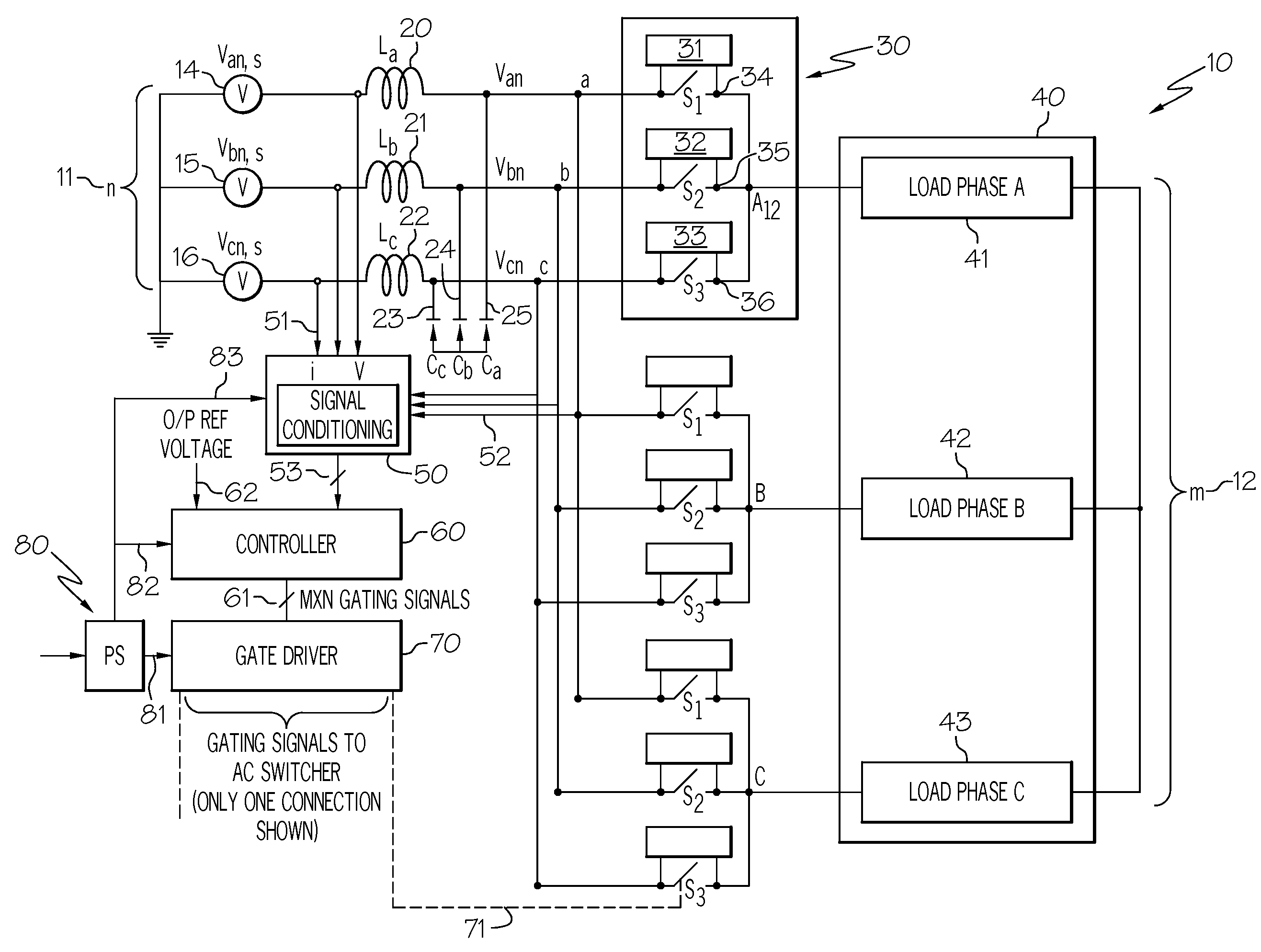
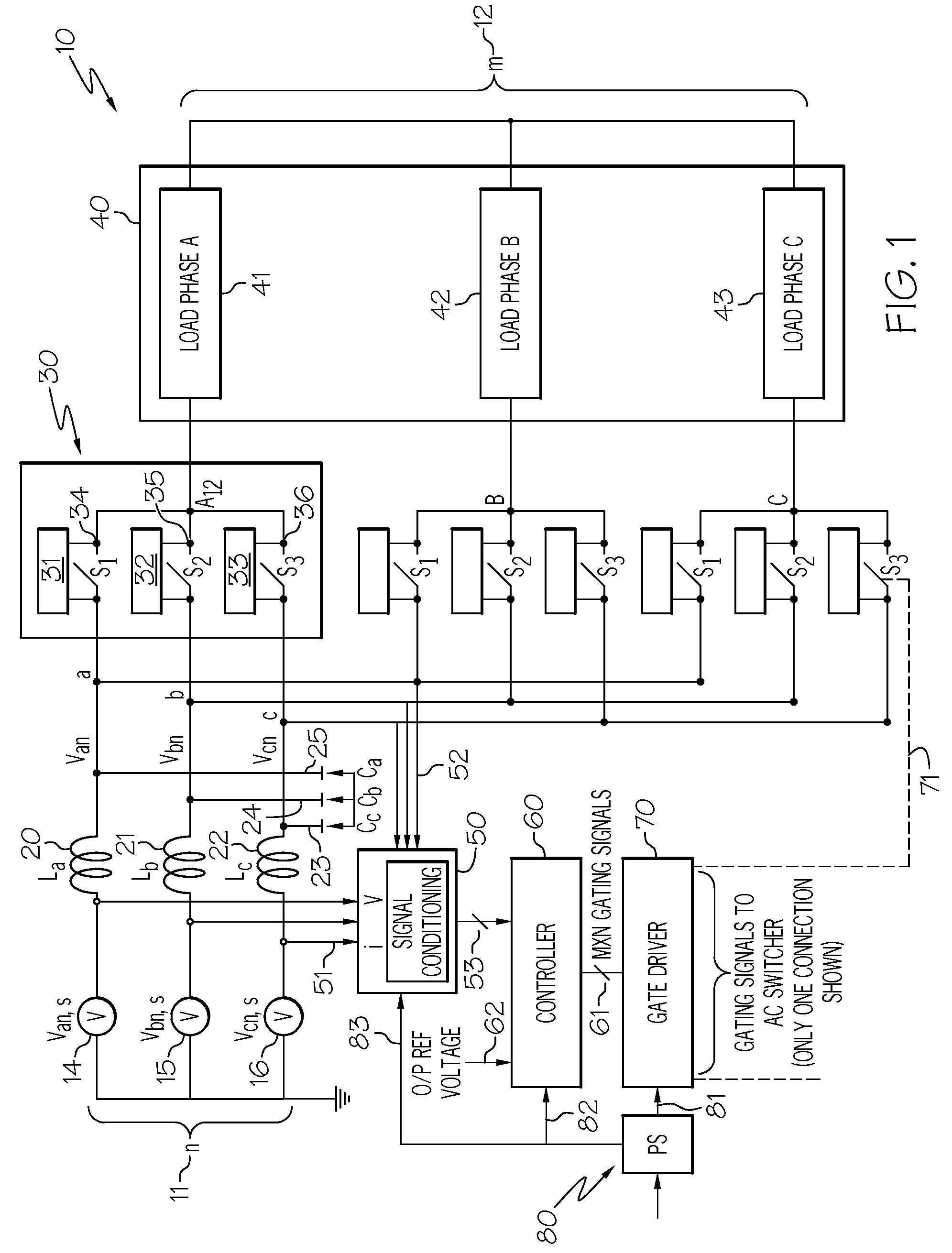
[0027]The following detailed description is of the best currently contemplated modes of carrying out the invention. The accompanying figures are simplified, not drawn to scale and are meant to include various direct AC-AC conversion applications with different electric power system input / output requirements. In the figures, each identical or substantially similar component that is illustrated in various figures may be represented by a single item or notation. Generalized control algorithms and block-diagrams are developed to reduce the number of figures required to show full operation. For purposes of clarity, not every component is labeled in every figure, nor is every component of each embodiment of the invention shown where illustration is not necessary to allow those of ordinary skill in the art to understand the invention. The description and accompanying figures are not to be taken in a limiting sense, but are made merely for the purpose of illustrating the general principles ...


PUM


Abstract

A matrix converter may be provided with AC switches that comprise bi-directional sets of semiconductor switches that are gated with a common gating link. A low loss diode-bridge based snubber may facilitate introduction of time delay between sequential operations of the bi-directional set of semiconductor switches. The matrix converter may be operated in a three-phase mode with only one gating signals for each AC switch, in contrast to prior-art matrix converters which may require use multiple gating signals for each AC switch.

Description

CROSS-REFERENCE TO RELATED APPLICATIONS[0001]This application claims the benefit of U.S. Provisional Application No. 60 / 917,871 filed May 14, 2007 which is incorporated by reference herein.BACKGROUND OF THE INVENTION[0002]The present invention is in the field of electrical power system control and, more particularly, control for Variable Speed Constant Frequency (VSCF) Electric Power Systems (EPS).[0003]In aircraft electrical power systems, power may be generated by electric machines that may be driven by prime movers such as aircraft engines. These prime movers may rotate at varying speeds and may cause their respective electric machines to produce electrical power at varying frequency. Variable frequency power generation (e.g., 360 to 800 Hertz (Hz)), may not be directly useful for supplying power to frequency sensitive loads.[0004]Various techniques may be employed to produce a substantially constant frequency in these above-described aircraft generating systems. Such techniques ...

Claims


Application Information

Patent Timeline
Patent Type & Authority Patents(United States)
IPC IPC(8): H02M5/45H02M5/458H02H7/122
CPCH02M1/32H02M5/271H02M5/273H02M5/293H02M2001/344H02M1/344
Inventor KOJORI, HASSAN ALI
Owner HONEYWELL INT INC
Why Eureka
Try Eureka