Method and apparatus for displaying stereographic images

a stereographic and image technology, applied in the field of methods and apparatus for displaying stereographic images, can solve the problem of not being able to assist in providing real-time stereographic information concerning a particular region in the terrain being mapped, and achieve the effects of reducing curvature or distortion, increasing overlap, and reducing apparent angl

Inactive Publication Date: 2011-09-22
MBDA UK
View PDF6 Cites 26 Cited by
  • Summary
  • Abstract
  • Description
  • Claims
  • Application Information

AI Technical Summary

Benefits of technology

[0029]The step of altering the image(s) may include increasing the overlap between the first and second images. In order to achieve this, the image acquired by the camera may cover an area significantly larger than that displayed in the stereographic image so that the areas of the first and second images not in common may be cropped. Cropping one or both of the images in this manner may allow the effects of unintentional camera movement (for example vibration) to be reduced.
[0030]The step of altering the image(s) may include rotating one or both of the first and second images to reduce the difference, if any, between the twist angle of the first and second images. (It will be understood that in the present context, the “twist angle” of a captured image is a measure of the angular position of the camera about the image vector of that captured image.) Again, in order to achieve this, the images acquired by the camera may cover an area significantly larger than that displayed in the stereographic image to enable the images to be transformed without reducing the size of the stereographic image displayed.
[0040]The apparatus may further include a switch arranged to cause switching of the display device between display of stereographic images by the display device and display of a 2-dimensional image display by the display device. The 2-D image may be provided by displaying only one image at a time, or by displaying two identical left and right images. The ability to switch between a 2-D image display, which may be familiar to a given human operator, and a 3-D image which may be unfamiliar to the operator but carry more information may enhance the usefulness and usability of the apparatus. The apparatus may thus provide all the functionality of a legacy system as well as the enhancements made possible by means of the present invention.

Problems solved by technology

The apparatus of WO03 / 032649 is thus able to map an area of terrain for subsequent analysis, including production of stereographic images, but can not assist in providing real-time stereographic information concerning a particular region in the terrain being mapped.

Method used


Image

  • Method and apparatus for displaying stereographic images
  • Method and apparatus for displaying stereographic images
  • Method and apparatus for displaying stereographic images

Examples


Embodiment Construction

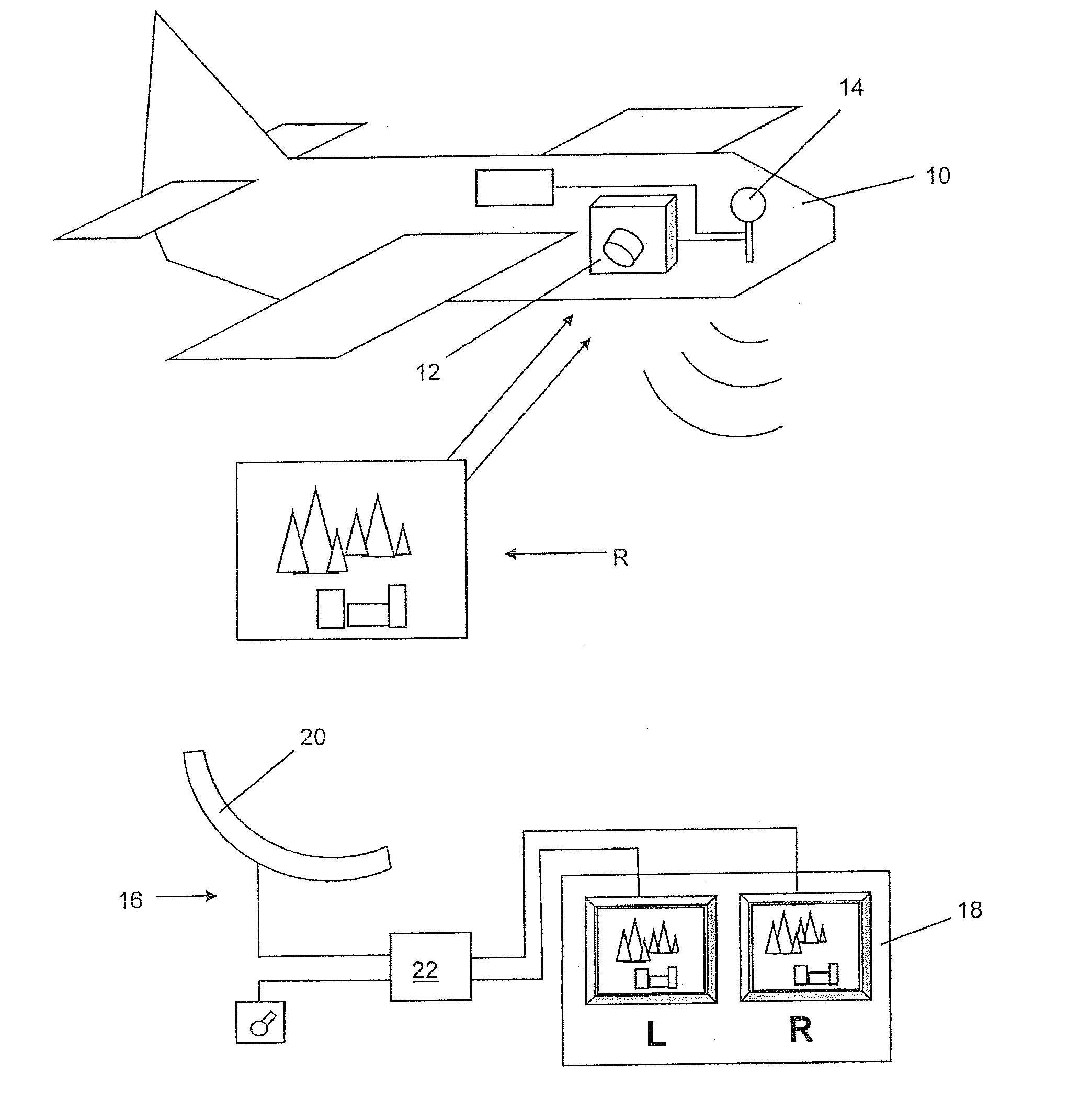
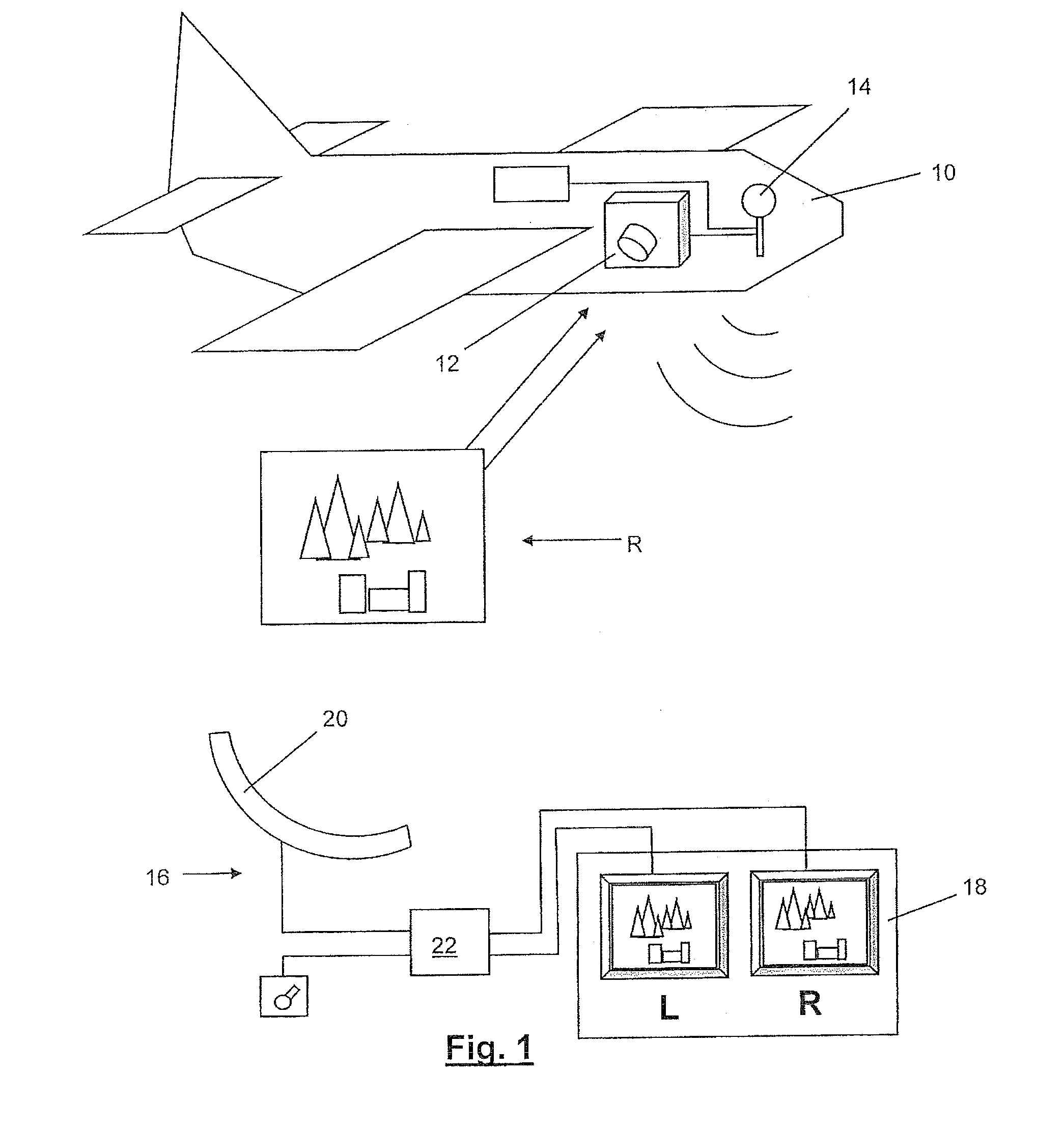
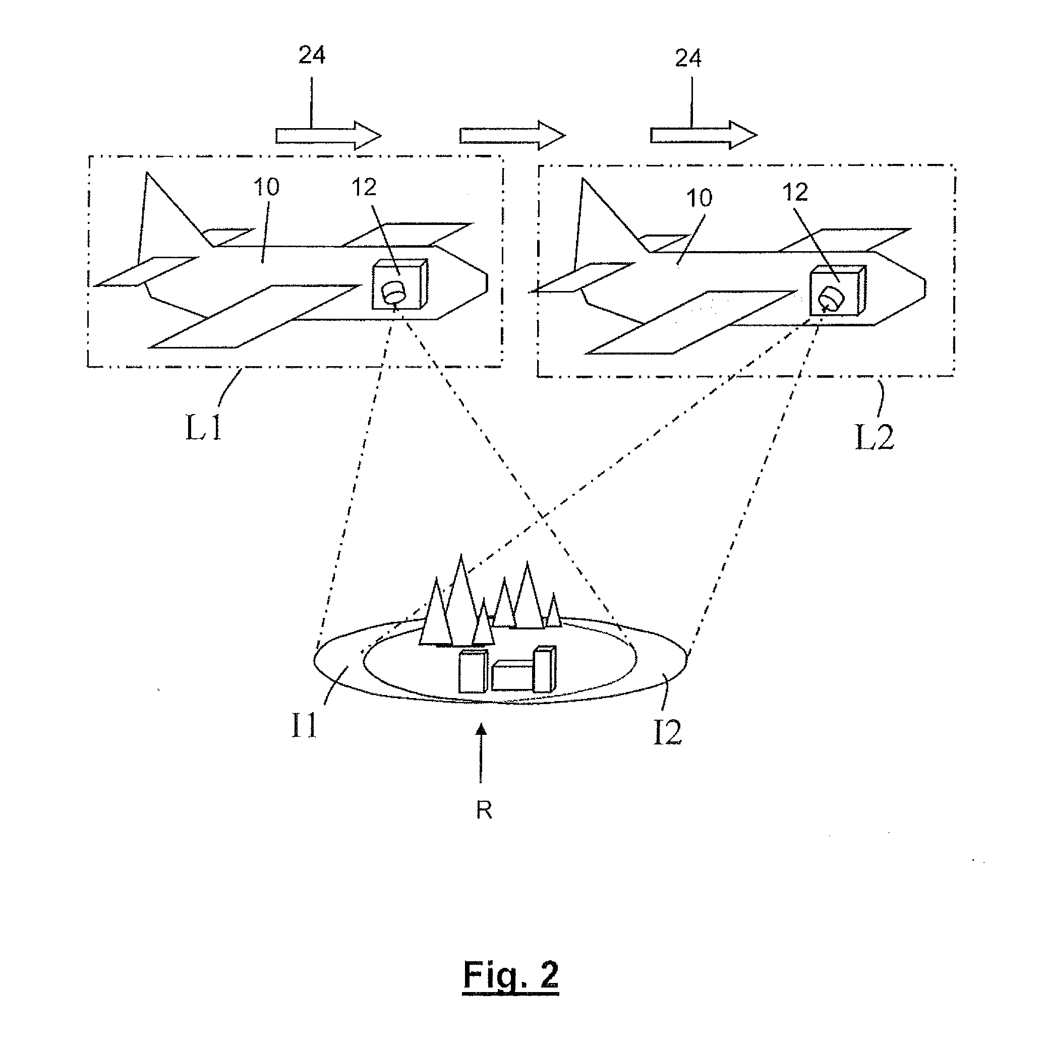
[0051]The embodiments of the invention illustrated by the accompanying drawings concern displaying to a remotely located operator stereographic images of a target region R surveyed by an unmanned aerial vehicle (UAV) in the form of a loitering missile. Typically, the vehicle will navigate a generally circular, or orbiting, path about the region R at its centre, however, the vehicle may navigate a straight path for at least some of its surveying time.

[0052]FIG. 1 shows a UAV 10 on board which there is provided a camera system 12. The camera system 12 comprises a single camera which is mounted for angular movement to track and acquire images of a target region R on the ground, typically about 600 m from the UAV 10. One factor in determining the distance that the UAV navigates from the target is the resolution of the camera system. The camera system currently adopted has a resolution such that 600 m is a typical viewing distance. However, with camera systems having greater resolution, ...


PUM


Abstract

The present invention relates to a method of displaying stereographic images of a region R. The method comprises: moving a vehicle (10) relative to the region, the vehicle carrying a camera system (12) for acquiring images I of the region; during movement of the vehicle relative to the region acquiring a series of temporally sequential multiple images (I1, I2, . . . ) of the region at respective multiple different spaced apart locations (L1, L2, . . . ) of the vehicle relative to the region; displaying successive stereographic images of the region during movement of the vehicle relative to the region. Each stereographic image comprises a first of said multiple images acquired at a first location and a second of said multiple images acquired at a second location which are temporally spaced apart in the series one from the other. The method comprises the step of varying the temporal spacing of the first of said multiple images and the second of said multiple images according to a velocity of the vehicle relative to the region so that the spatial separation between the first and the second locations is not less than a predetermined amount so that the stereographic images having a required depth can be displayed independent of the velocity of the vehicle relative to the region.

Description

[0001]The present invention relates to a method and apparatus for displaying stereographic images of a region. For example, an embodiment of the present invention relates to displaying to a remotely located operator a target region surveyed by an unmanned aerial vehicle (UAV) in the form of a loitering missile.BACKGROUND OF THE INVENTION[0002]It is known to capture real-time 2-D images by means of a camera carried by an unmanned aerial vehicle (UAV) and to transmit those images to a remote location for display on a display device. A human operator may then view the images at the remote location. Such a system can be used in connection with loitering airborne munitions to enable an operator to detect, recognise and identify a target. Current systems use 2-D images relayed to the operator for target re-acquisition decision making where the perception of perspective and depth is limited. The present invention is concerned with a system and method that enables the afore-described real-t...

Claims


Application Information

Patent Timeline
Patent Type & Authority Applications(United States)
IPC IPC(8): H04N13/02H04N13/00H04N13/221H04N13/211
CPCH04N13/0221H04N13/221H04N13/211
Inventor MARKHAM, KEITH CHRISTOPHERGATE, MARTIN SIMON
Owner MBDA UK
Why Eureka
Try Eureka