Fire door stop system

a technology for stopping doors and fire doors, applied in the field of fire doors, can solve the problems of excessive clearance between the edge of the labeled fire door and the labeled door frame, increasing imperfections, and contributing to the formation of excessive clearan

Active Publication Date: 2014-09-18
NOBLE III CHARLES A
View PDF27 Cites 22 Cited by
  • Summary
  • Abstract
  • Description
  • Claims
  • Application Information

AI Technical Summary

Benefits of technology

[0009]The invention is a fire door stop system for use on steel or wood fire door assemblies. The fire door stop system according to the invention, also referred to as a “profile system,” is installed on door labeled fire door frames of labeled fire door assemblies and increases the overlap between the fire door and the door frame. The profile system according to the invention corrects excessive clearances on fire door assemblies, which would otherwise fail a safety inspection and void the label on the labeled fire door assembly, and brings them into compliance with the fire safety codes.
[0013]The fire door stop system according to the invention, i.e., the fire door stop and, as needed, the edge protectors, latch protector, and the fire-door extension, guarantees proper performance of the fire door, which is an integral part of a life-safety protection system. The fire door stop system accommodates the typical business practice of manufacturing to minimum standards and imperfections in manufacturing and installation.

Problems solved by technology

Unfortunately, the doors and door frames are built to the minimum standards and, if the installation isn't perfect, the clearance between the edge of the labeled fire door and the labeled door frame may be excessive, such that the overlap is less than specified or that a gap exists between the edge of the door and the edge of the frame.
The overwhelming majority of the failures are due to excessive clearance between door and door frame.
Also, buildings settle over the years, increasing imperfections in the installation and contributing to the formation of an excessive clearance.
Replacing the door and / or frame is not only costly, but may be nearly impossible.
Even the less invasive remedy of shimming the door frame can be impossible in this case.
If it is possible to shim the door, this means pulling the door from the hinge side toward the lock side, which then frequently creates an excessive clearance on the hinge side.

Method used


Image

  • Fire door stop system
  • Fire door stop system
  • Fire door stop system

Examples


Embodiment Construction

[0033]The present invention will now be described more fully in detail with reference to the accompanying drawings, in which the preferred embodiments of the invention are shown. This invention should not, however, be construed as limited to the embodiments set forth herein; rather, they are provided so that this disclosure will be complete and will fully convey the scope of the invention to those skilled in the art.

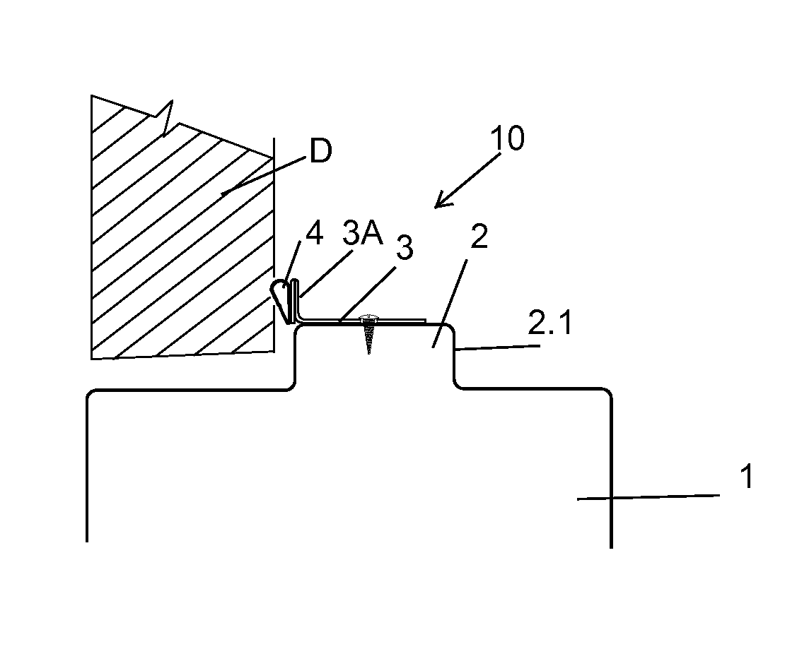
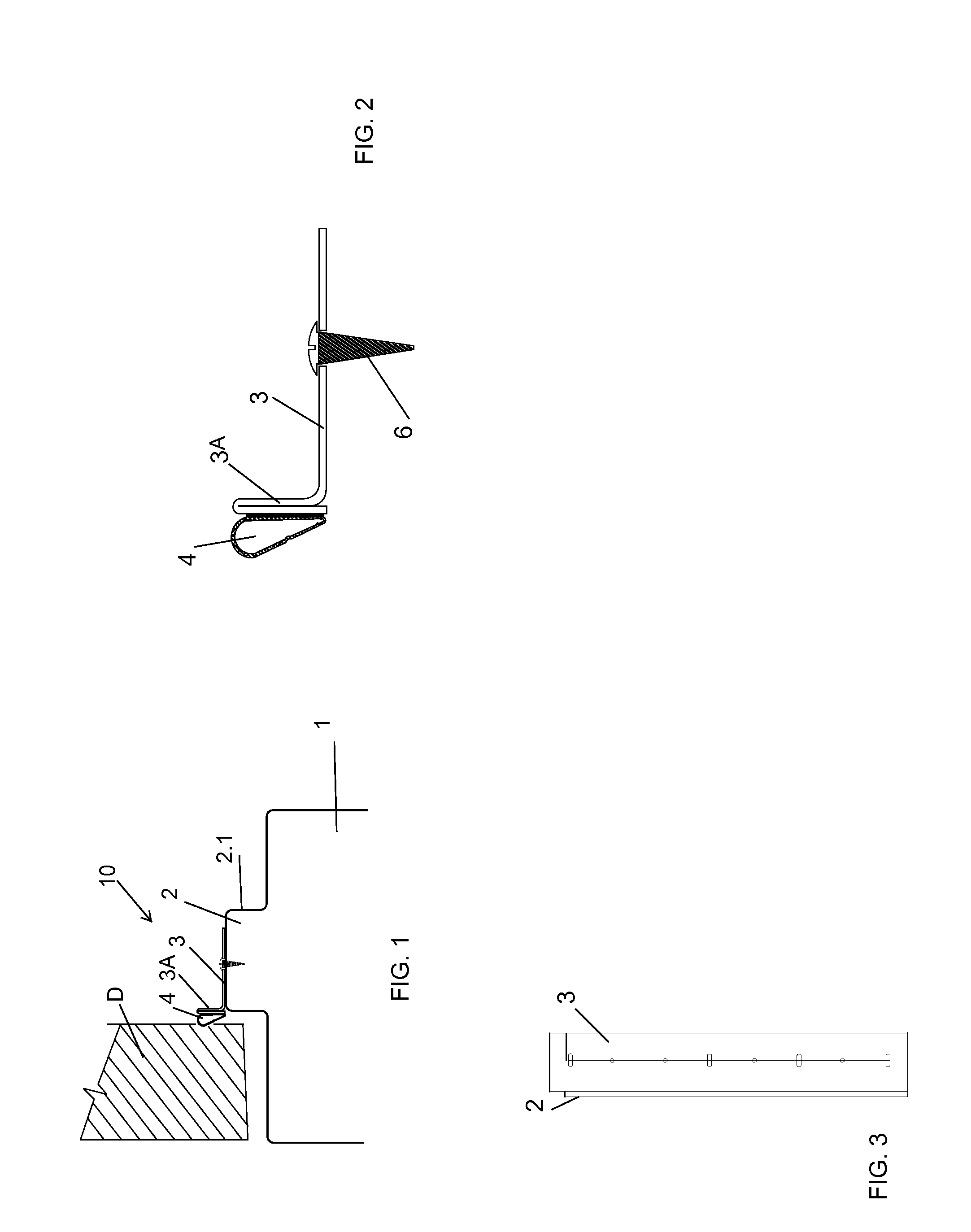
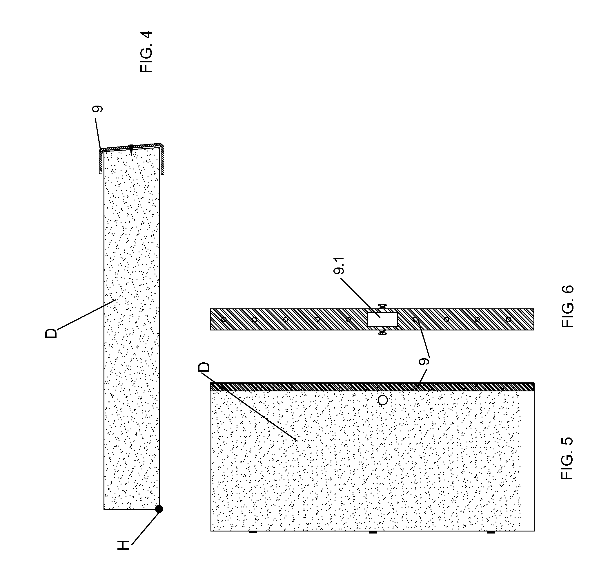
[0034]FIGS. 1-6 illustrate a fire door stop system 10 according to the invention that is used with a fire door assembly, to ensure that the assembly remains compliant with fire safety codes. A fire door assembly that is compliant includes a labeled fire door D and a labeled fire door frame 1. FIG. 1 shows a partial section of a fire door assembly, i.e., a conventional labeled fire door D and a conventional labeled fire door frame 1 with a soffit 2. The door D is closed. The soffit 2 has a standard soffit height 2.1 of ⅝ inch. As shown in the figure, there is a gap betwee...


PUM


Abstract

A fire door stop system for retrofitting a fire door assembly so as to bring the assembly into compliance with fire safety codes. The fire door stop system has a profile strip that is attachable to a fire door frame. An edge of the profile strip extends outward from the frame in a line with a face of the soffit against which the pull edge of the fire door closes. The fire door stop system further includes, as needed, edge protectors for a wood fire door, such as a horizontal edge protector, a vertical edge protector, and a bottom-edge extender, and a latch protector.

Description

BACKGROUND INFORMATION[0001]1. Field of the Invention[0002]The invention relates to fire doors. More particularly, the invention relates to a fire door stop to stop the spread of smoke, hot gases, or fire from flowing between a fire door and the door frame.[0003]2. Discussion of the Prior Art[0004]The National Fire Protection Association (NFPA) develops codes and standards that minimize the risk and effects of fire and other hazardous situations. NFPA 80 regulates the installation and maintenance of assemblies and devices used to protect openings in walls, floors, and ceilings and as of 2007 requires that all doors and door frames that are labeled fire doors and labeled fire door frames be inspected and tested annually. This standard is herein incorporated in its entirety by reference. NFPA 80 specifies the allowable clearances or gaps between fire door and frame and the floor. Currently, the specified clearance between door and frame is ⅛ inch, plus or minus 1 / 16 inch, for steel do...

Claims


Application Information

Patent Timeline
Patent Type & Authority Applications(United States)
IPC IPC(8): E06B5/16
CPCE06B5/164E06B3/88
Inventor NOBLE, III, CHARLES A.
Owner NOBLE III CHARLES A
Why Eureka
Try Eureka