

Illuminating a specimen for metrology or inspection
- Summary
- Abstract
- Description
- Claims
- Application Information
AI Technical Summary
Benefits of technology
Problems solved by technology
Method used
Image

Examples
Embodiment Construction
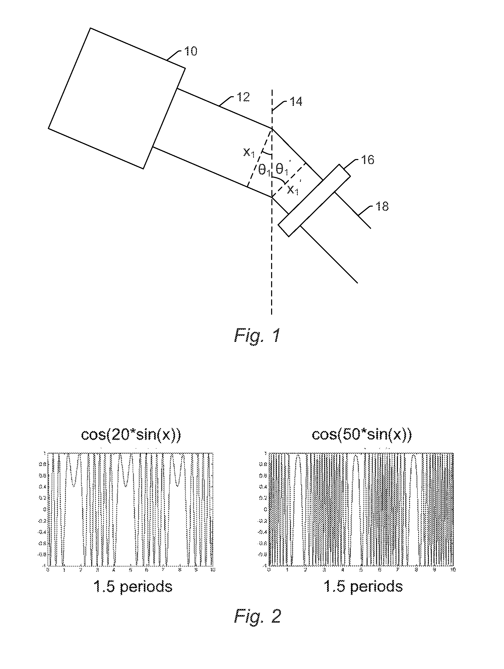
[0021]Turning now to the drawings, it is noted that the figures are not drawn to scale. In particular, the scale of some of the elements of the figures is greatly exaggerated to emphasize characteristics of the elements. It is also noted that the figures are not drawn to the same scale. Elements shown in more than one figure that may be similarly configured have been indicated using the same reference numerals.
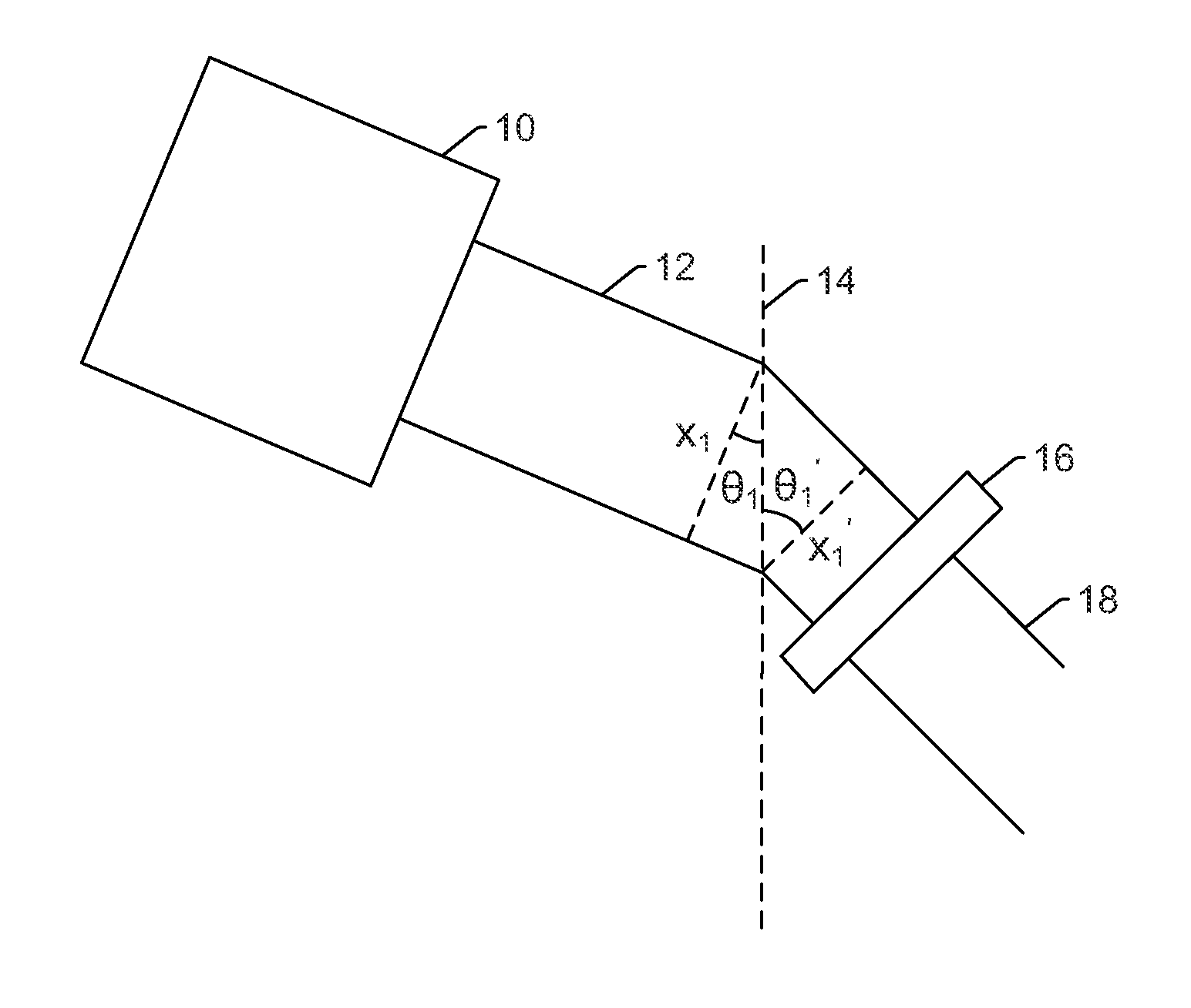
[0022]In general, the embodiments described herein relate to speckle suppression approaches for pulsed laser light sources. For example, the embodiments described herein provide a solution for suppression of speckle patterns produced by a coherent pulsed light source (a pulsed laser). In some embodiments, the specimen may be a wafer such as that on which semiconductor devices are or can be fabricated. In addition, although some description is provided herein with respect to a wafer or wafers, it is to be understood that the embodiments described herein can be used to illuminat...
PUM
 Abstract
Description
Claims
Application Information