Device for determining a filling level

a technology of filling level and device, which is applied in the direction of measuring device, level indicator, instruments, etc., can solve the problems of long time period and impaired determination of determined values

Active Publication Date: 2011-09-22
HELLA KG HUECK & CO
View PDF10 Cites 18 Cited by
  • Summary
  • Abstract
  • Description
  • Claims
  • Application Information

AI Technical Summary

Benefits of technology

[0016]According to another embodiment, the pre-chamber is improved compared with the prior art. The pre-chamber has at least two levels lying horizontally one over another, and the levels are flowed through in opposite directions to each other. In particular, the change in flow direction caused by the levels which are flowed through in opposite directions to each other leads to the result that even highly foamed fluids and oil foam in the case of sudden turbulences, e.g. by changes to rotation speed in the pre-chamber are decelerated so intensively that a degassing is possible. The individual levels are preferably able to be flowed through by the fluid from top to bottom and then enter into the measurement section of the stillwell.

Problems solved by technology

The determined values would then be impaired over a lengthy period of time.

Method used


Image

  • Device for determining a filling level
  • Device for determining a filling level
  • Device for determining a filling level

Examples


Embodiment Construction

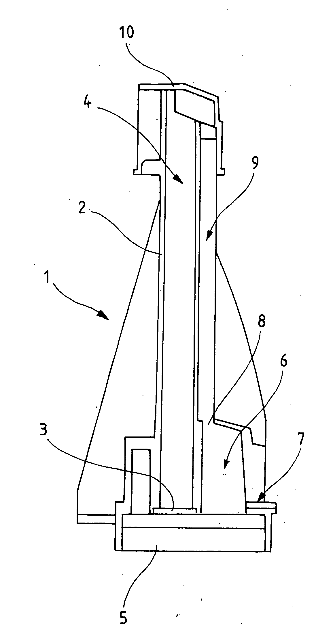
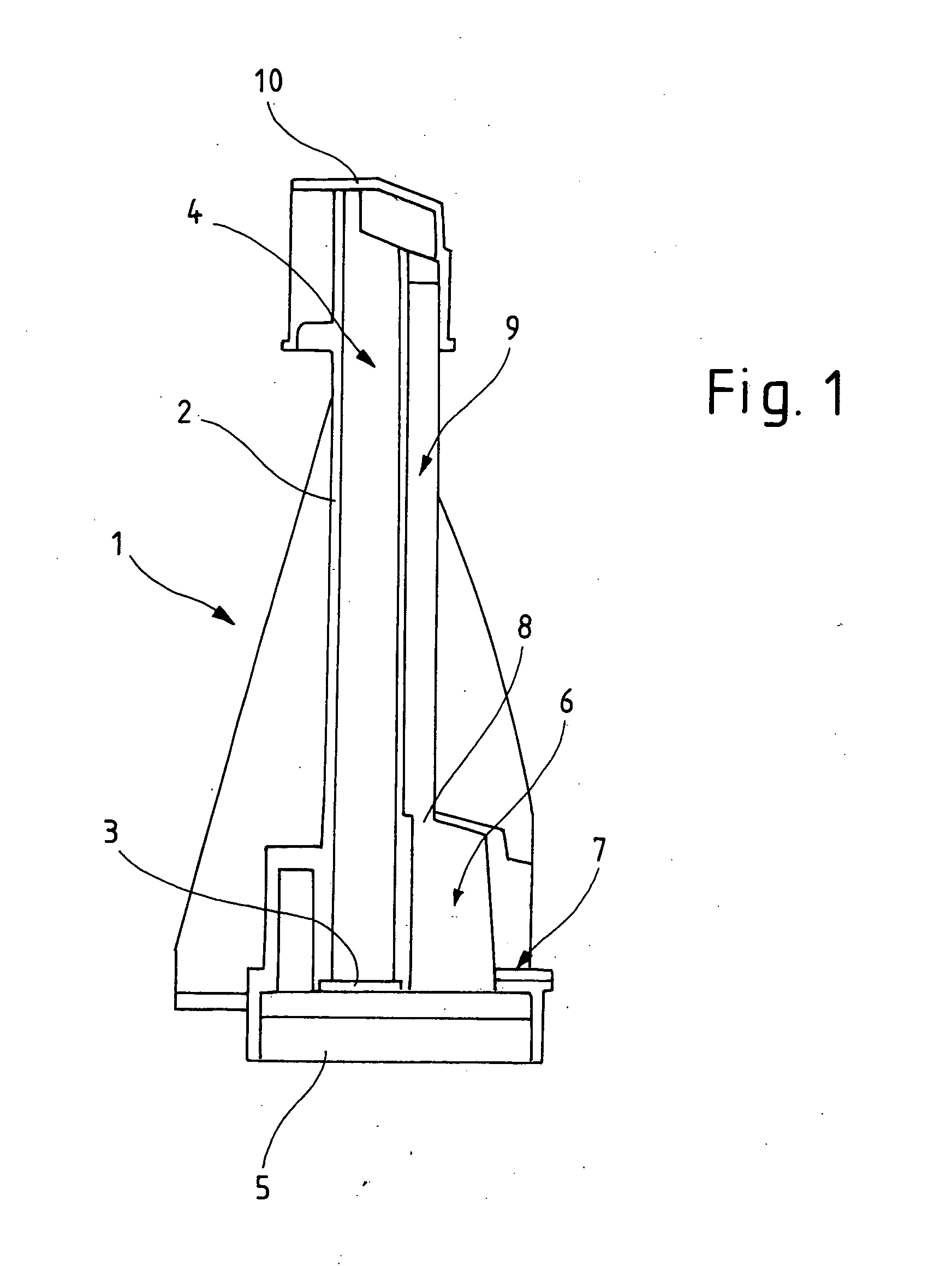
[0032]A device 1 according to the invention for determining the filling level in a container has in the base region an ultrasonic sensor 3. This ultrasonic sensor 3 is arranged on a base element 5 of device 1. A stillwell 2 is arranged centrally over ultrasonic sensor 3, with the stillwell 2 having a measurement section 4 in the interior. With a filled container, this measurement section 4 is occupied by fluid, in particular oil in an oil sump of a motor vehicle, depending on the filling level of the container. Ultrasonic sensor 3 and measurement section 4 are arranged in a line one over the other, with ultrasonic sensor 3 sending the generated sound waves into measurement section 4 of stillwell 2. In order to obtain correct measurement values, ultrasonic sensor 3 and measurement section 4 are arranged perpendicularly to the horizontal.

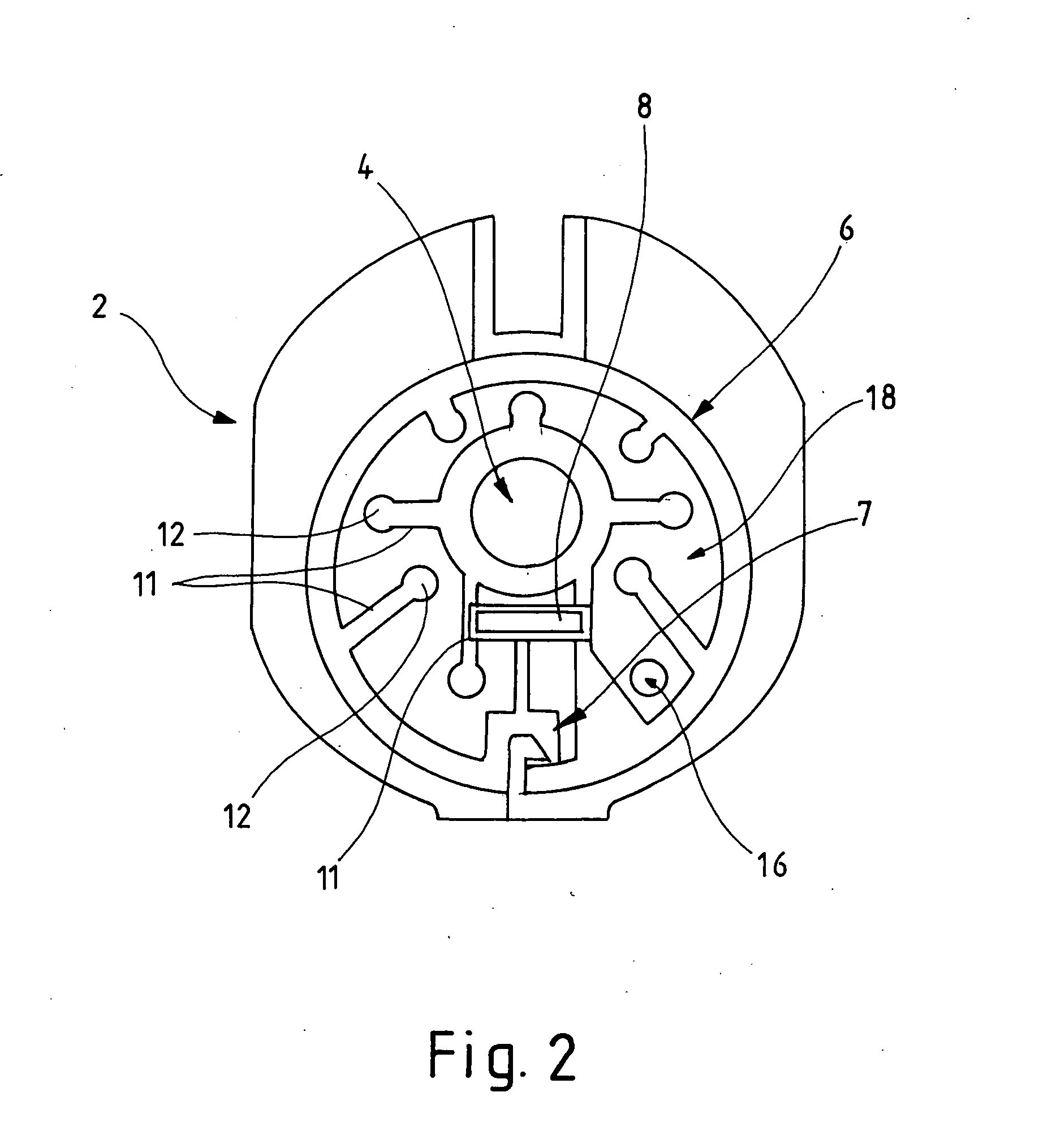
[0033]A pre-chamber 6, with an inlet opening 7 to the container and with two outlet openings, of which only one outlet opening 8 is illustrated in FI...


PUM


Abstract

A device for determining a filling level in a container, with a stillwell which has an entry opening and a vent opening, an ultrasonic transducer arranged in the base region of the stillwell and at least one pre-chamber. The pre-chamber has an inlet opening to the container and an outlet opening to the entry opening of the Stillwell. The pre-chamber of the device has a second outlet opening that opens out in a lead-off arrangement. By the lead-off arrangement, foamed medium flowing in quickly and suddenly into the pre-chamber of the device does not arrive into the measurement section of the ultrasonic transducer.

Description

CROSS REFERENCE TO RELATED APPLICATIONS[0001]Applicant claims priority under 35 U.S.C. §119 of German Application No. 10 2010 011 492.8 filed Mar. 16, 2010, the disclosure of which is incorporated by reference.BACKGROUND OF THE INVENTION[0002]The invention concerns a device for determining a filling level in a container, with a stillwell which has an entry opening and a vent opening, with an ultrasonic transducer arranged in the stillwell and with at least one pre-chamber. The pre-chamber has an inlet opening to the container and an outlet opening to the entry opening of the stillwell.[0003]In order to determine the oil level in engines, ultrasonic sensors are predominantly used. These emit sound waves which can be measured at the interface between two media, e.g. gas and oil, wherein other fluids can also be measured instead of oil, reflected and received again by the ultrasonic sensor. From the detected run time of the sound waves, the filling level can then be determined in the c...

Claims


Application Information

Patent Timeline
Patent Type & Authority Applications(United States)
IPC IPC(8): G01S15/00
CPCG01S15/88G01F23/2962
Inventor NIEMANN, THOMAS
Owner HELLA KG HUECK & CO
Why Eureka
Try Eureka