Fiber optic cables and assemblies for fiber toward the subscriber applications

Active Publication Date: 2011-09-22
CORNING OPTICAL COMM LLC
47 Cites 67 Cited by

AI-Extracted Technical Summary

Problems solved by technology

For example, the fiber optic cable can encounter rough terrain or rough ...

Benefits of technology

[0015]According to the above and other aspects, fiber optic cables are rugged so that they can absorb radial compressions, such as wh...

Abstract

Fiber optic cables and assemblies for routing optical networks closer to the subscriber. The fiber optic cables have a small-cross section yet robust design that is versatile by allowing use in aerial application with a pressure clamp along with use in buried and/or duct applications. Additionally, the fiber optic cables and assemblies have a relatively large slack storage capacity for excess length. Assemblies include hardened connectors such as plugs and/or receptacles suitable for outdoor plant applications attached to one or more ends of the fiber optic cables for plug and play connectivity.

Application Domain

Fibre mechanical structures

Technology Topic

Plug and playRobust design +4

Image

  • Fiber optic cables and assemblies for fiber toward the subscriber applications
  • Fiber optic cables and assemblies for fiber toward the subscriber applications
  • Fiber optic cables and assemblies for fiber toward the subscriber applications

Examples

  • Experimental program(2)

Example

Example 1
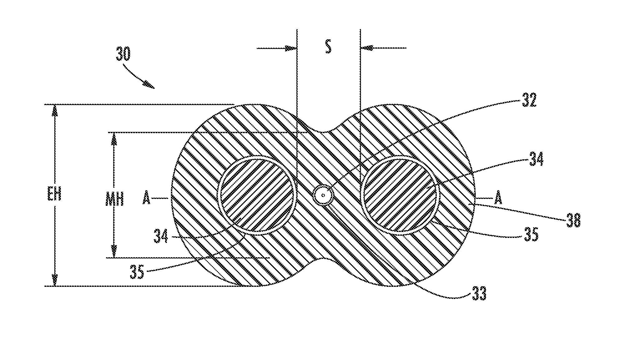
[0106]A fiber optic cable 610 as illustrated in FIG. 20 has a height of 3 millimeters, a width W of 5.3 millimeters, a separation distance S1 of 2.3 millimeters, strength components 630 each with a radius R1 of 0.625 millimeters, a medial height MH of 2.5 millimeters, an end height EH of 3 millimeters, and a height ratio MH/EH of 0.833. The cable jacket 640 is constructed from MDPE (Medium Density Polyethylene), the strength components 630 are constructed from GRP (Glass Reinforced Plastic), the adhesion promoter 654 is EAA (Ethylene Acrylic Acid), and the optical fiber 620 has a diameter of 0.255 mm (including a 0.01 mm color coating).
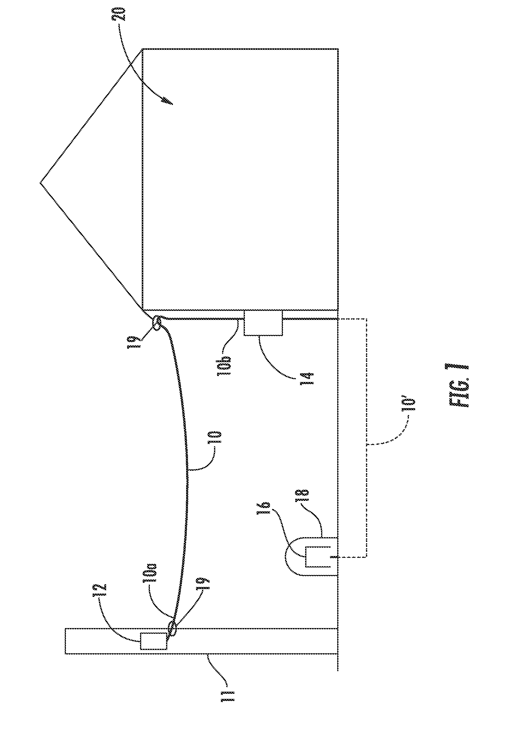
[0107]According to another aspect of the present embodiment, the small cross-sectional footprint of fiber optic cable 610 allows for a smaller coil diameter compared with conventional fiber optic cables. Consequently, relatively long lengths of the fiber optic cable 610 can be stored in a relatively small volume. For example, the volume occupied in coiling 60 meters of the fiber optic cable 610 can be less than about 5000 cubic centimeters. The small size of the fiber optic cable 610 also allows for relatively large lengths of slack storage in small spaces for aerial installations and/or buried installations. The weight, for example, of a kilometer of the cable 610 can be less than 19 kilograms.
[0108]Despite its small size and weight and high storage capacity, the fiber optic cable 610 is robust and capable of being GR-20, RDUP, IEC, and/or ICEA compliant. The cable 610 may be, for example, resistant to crush loads such as those exerted by a pressure clamp. FIG. 21A is a plot simulating induced radial stresses on an optical fiber in a cable having a cross-section of the same shape as the cable 610 (FIG. 20) under varying crush force values. FIG. 21B is a stress-strain curve used to model jacket material. In FIG. 21A, model crush data for a flat cable such as the comparison cable illustrated in FIG. 4 is included for comparative purposes. The crush data for the test cable having the cross-section illustrated in FIG. 20 is the lower line 662 and the crush data for the flat comparison cable is the upper line 664. The fiber stresses are indicated on the vertical axis in Pascals, and the applied crush forces are indicated as force values on the horizontal axis in Newtons per millimeter of crushed cable length. The stress-strain curve used to model the jacket material is illustrated in FIG. 21B. The applied forces on the cables are modeled as being applied by smooth crush plates.
[0109]FIG. 22 is a plot simulating induced radial stresses on an outer periphery of the optical fiber in a cable having a cross-section of the same shape as the cable 610 (FIG. 20) under varying crush displacement values. The crush data for the test cable having the cross-section illustrated in FIG. 20 is the lower line 666 and the crush data for the flat comparison cable is the upper line 668. The fiber stresses are indicated on the vertical axis in Pascals, and the applied displacements are indicated as distance values on the horizontal axis in millimeters. The displacement values simulate the distances that upper and lower surfaces of a cable are depressed inwardly under applied loads. For example, an induced displacement of 0.5 mm would result in a 0.5 mm reduction in the total or end height EH of the cable 610 shown in FIG. 20.
[0110]As indicated by the simulation data of FIGS. 21A, 21B and 22, the optical fiber or fibers in cables according to the present embodiments experience lower stresses and radial displacements under crush loads than conventional flat cables, in additional to smaller footprints. Reduction of stresses on and displacements of the optical fiber preserves the optical performance of the fibers, such as, by example, reducing bending of the fiber. Referring back to FIG. 20, the recessed portions 658 of the cable jacket in part act to reduce or inhibit the transference of stresses to the fibers, which are induced by loads applied to the upper and lower surfaces of the end portions 650, to the optical fiber 620 located in the medial region 646. Instead, the majority of the crush loads/stresses are borne by the strength components 630 and the surrounding jacket material. Referring to the simulation data of FIG. 21A, radial stresses in the fiber induced by applied crush loads (i.e., pressures) of up to 100 N/mm are less than about 30 MPa, radial stresses for applied crush loads of up to 80 N/mm are less than about 30 MPa, in the range of 27 MPa, and radial stresses for applied crush loads of up to 60 N/mm are less than 20 MPa, in the range of about 18 MPa. Referring to the simulation data of FIG. 22, fiber radial stresses induced by applied crush displacements of up to 0.4 mm are less than 15 MPa, radial stresses for applied crush displacements of up to 0.5 mm are less than about 19 MPa, and radial stresses for applied crush displacements of up to 0.6 mm are less than about 25 MPa.
[0111]FIGS. 23 and 24 respectively illustrate cable cross-sections for cables 710, 810 of similar composition and geometry to the cable 610 with toneable elements 770, 870 included thereon. The toneable elements 770, 870 can be included for locating the fiber optic cables such as when they are buried. The toneable elements 770, 870 may be any suitable conductive material useful for determining the location of the fiber optic cable, such as a small conductive copper wire, copper-clad steel, a printed conductive strip, or the like. By way of example, the illustrated toneable elements 770, 870 are metallic copper wires having a gauge between 20-42 AWG.
[0112]Referring to FIG. 23, the fiber optic cable 710 has a toneable element 770 of radius R4 disposed within a toneable lobe 774 that is separable from a main cable body 778. The cross-section and composition of the main cable body 778 can be essentially the same as the cross-section of the cable 610. The toneable lobe 774 is attached to the jacket 776 of the main cable body 778 by a breachable web 780 that is easily separable by hand, thereby making it craft-friendly. The toneable lobe 774 includes polymeric material that can be integral with the cable jacket. The web 780 has minimum thickness T1 and can be connected by a curved surface generally having the shape of an arc with radius R5. The main cable body 778 is delineated from the web 780 by a dashed line. The web 780 can also include a preferential tear portion/geometry (not numbered) for controlling the location of the tear in the web near main cable body 778, thereby resulting in a “clean” separation. The main cable body 778 and the toneable lobe 774 may be extruded through the same extrusion tooling and using the same polymer extrudate. The total footprint or cross-sectional area AT of the main cable body 778, and the radius R2 of strength components 790 can fall within the same ranges as the cable 610.
[0113]Referring to FIG. 24, the fiber optic cable 810 has a toneable element 870 of radius R4 disposed within a toneable lobe 874 that is separable from a jacket 876 of the main cable body 878. The cross-section and composition of the main cable body 878 can be essentially the same as the cross-section of the cable 610. The toneable lobe 874 is attached to the main cable body 878, delineated by the dashed line, by a breachable web 880 that is easily separable by hand. The web 880 has minimum thickness T2 and can be connected by a curved surface generally having the shape of an arc. The main cable body 878 and the toneable lobe 874 may be extruded through the same extrusion tooling. The total footprint of cross-sectional area AT of the main cable body 878, and the radius R2 of strength components 890 can fall within the same ranges as the cable 610.
[0114]Both cable main bodies 778, 878 that may be substantially identical in cross-sectional shape, width W, height ratio MH/EH, jacket area AJ, and total area to the fiber optic cable 610 (FIG. 20), and the respective components of the cables 710, 810 may be constructed of the same or similar materials to that of the cable 610. Accordingly, the resistance to crush forces and displacement loads afforded the optical fibers 720, 820 may be similar or identical to the data illustrated in FIGS. 21A, 21B and 22. Further, each of the properties and dimensions may fall in the ranges ascribed to the cable 610.

Example

Example 2
[0115]A toneable fiber optic cable 810 as illustrated in FIG. 24 has a height of 3 millimeters, a main body 878 width of about 5.4 millimeters, an overall with W of 6.6 mm, a separation distance between strength components centerlines of 2.3 millimeters, strength components 630 each with a radius R1 of 0.625 millimeters, a medial height MH of 2.5 millimeters, an end height EH of 3 millimeters, a height ratio MH/EH of 0.833, and a minimum neck thickness T2 of about 0.6 millimeters. The cable jacket 840 is constructed from MDPE, the strength components 830 are constructed from GRP, the adhesion promoter 654 is EAA, and the optical fiber 820 has a diameter of 0.255 mm (including a 0.01 mm color coating layer). The jacket area AJ, excluding the toneable lobe, is about 10 millimeters squared.
[0116]The optical cables constructed according to the present embodiments can be constructed to have additional desirable properties. For example, the jacket materials may be extruded such that the cable jacket contacts or is directly adjacent to the optical fiber or fibers and the strength components in the cable. The term “directly adjacent to” in the context of the fibers means there is no intervening element (such as a buffer tube) between the jacket and fibers (or a tight buffer layer on a fiber). It allows for continuous or intermittent contact and some adherence of fibers with the jacket cavity, while the contact need not be continuous (e.g., it may be intermittent) at the fiber-jacket interface along the length of the cable. The term “directly adjacent to” does allow, however, for the presence of water-swellable powder, for example, in the jacket cavity with the fibers. Further, the excess fiber length (EFL) may be controlled to induce a desired strain level to remain in the optical fiber after manufacture of the cable. In addition, extrusion of the cable jacket can be controlled so that forces required to pull fibers from the cable are not excessive.
[0117]FIG. 25 is a schematic representation of an exemplary manufacturing line 900 for making fiber optic assemblies according to the present invention. The manufacturing line 900 may include one or more rotating reels 920 for paying out one or more optical fibers 922 along a process direction 912. Other means, such as flying off, may also be used to pay off one or more optical fibers. The illustrated manufacturing line 900 illustrates a process utilizing a single optical fiber 922, but other numbers, including 2, 4, 6, etc., of optical fibers, or groups of fibers arranged in ribbons, for example, can be used.
[0118]Still referring to FIG. 25, the fiber 922 passes into an extrusion apparatus 930. In general, the extrusion apparatus 930 extrudes a jacket around the fiber 922, which draws down around the fiber to form uncooled fiber optic assembly 934. The fiber 922 may be preheated in a preheater prior to entering the extrusion apparatus 930 to provide lower strain variation in the fiber, a smoother surface of the surrounding jacket, and may result in lower attenuation. Without being bound by theory, applicants believe preheating removes volatiles in the fiber coating to improve cable properties. Slowing the extrusion process can also be used as the hot extrusion head may act effectively as a preheater of the fiber. The uncooled fiber optic assembly 934 may then be cooled in a cooling device 950, which may be, for example, a longitudinally extending trough filled with cooling fluid, such as liquid water. The cooling device 950 cools the recently extruded jacket as the fiber optic assembly 934 moves along the process direction 912. The resultant fiber optic assembly 960 is then collected on a take-up device 968, such as, for example, a take-up reel.
[0119]The optical fiber or fibers 922 may be subject to controlled tensioning during manufacturing so that an increased tension or strain resides in the fiber after manufacturing. The tension is imparted to the fiber during manufacturing by optical fiber payoff with a tension range from 100 to 400 g-force. The ultimate strain in the fiber or fibers can be in the range of 0.0-0.2%, or, equivalently, a range of −0.2-0.0% excess fiber length at room temperature (25° C.). According to one aspect of the present embodiments, the optical performance of cables having optical fibers of higher tension/strain have reduced levels of optical attenuation. The residual strain, for example, can prevent buckling of the fiber within the relatively small cavity of the cable jacket.
[0120]According to another aspect of the present embodiments, the cables can be constructed such that forces required to pull fibers from the cable are not excessive. One aspect of the present embodiments is that the cable jacket may be directly adjacent to or in direct contact with the optical fiber or optical fibers of the cable. This configuration is shown by the exemplary cable 610 in FIG. 20. Water penetration in the cable is thereby mitigated or eliminated and the cable may have a small cross-section. In such a configuration, however, the adhesion between the jacket and fiber(s) must be controlled so that the optical fiber can be pulled from the cable jacket for connectorization, etc. Without being bound by theory, applicants believe the small cross-section of the cable allows the extruded jacket to cool very quickly, before the jacket adheres excessively to the fibers therein. Removal forces for the fiber(s) are thereby maintained within desired ranges. Table 2 tabulates peak removal forces of optical fiber from an optical cable as illustrated in FIG. 20, including variations having a toneable lobe as illustrated in FIG. 24.
TABLE 2 Peak Removal Force Pull Speed Removal Standard Test Cable Cable Type (meters/minute) Force (lbs) Deviation #54 dielectric 20 1.5 (0.5) #54 dielectric 200 0.9 (0.8) #59 toneable 20 1.3 (1.2) #59 toneable 300 1.3 (1.5) #68 toneable 300 .037 (.04) #79 toneable 20 2.5 (2.5) #80 dielectric 20 6.8 (1.5) #80 dielectric 200 7.7 (2) #82 dielectric 20 2.2 (0.7) #82 dielectric 300 0.02 (0.06) #82 dielectric 20 0.3 (0.6) #82 dielectric 300 0.03 (0.04)
[0121]FIGS. 26 and 27 illustrate the method used to measure peak removal force, including the method for preparing a cable sample for measurement. The tested cable illustrated in FIGS. 26 and 27 corresponds to the cable 610 illustrated in FIG. 20. Peak removal force is measured using a load cell machine 990 (FIG. 27). The load cell machine 990 may be a Model 4201 load cell machine available from Instron® of Norwood Mass. In order to prepare the cable 610 for removal force testing, the cable is held in one hand, and the sides of the jacket 640 are cut away to expose the strength components 630, as shown in FIG. 26. A length of 0.5 meters of the jacket sides can be cut away. The strength components are separated from the jacket and cut back from the end of the cable. The cable end is cut in the grooves where the strength members were previously located, and the cable jacket halves are pulled to separate the jacket along the length of cable. The separated jacket halves can then be cut away to expose the fiber 620. Any remaining jacket and the strength components can be cut away so that the exposed fiber extends from the end of the cable. The opposite end of the cable sample is prepared by cutting a predetermined distance back from the exposed end of the cable. Referring to FIG. 27, the cable sample is placed in the testing machine 990. The jacket side of the cable is placed in one set of grips 1010 and the optical fiber 620 is held between the opposed set of grips 1020. The desired pull speed is set, and the machine 990 is run to record the peak force required to pull the fiber until the fiber is completely removed from the cable.
[0122]Referring back to Table 2, embodiments of the present invention are constructed to have pull out forces of less than 15 lbs using the above-described testing methodology. According to one embodiment, pull out forces are less than 11 lbs, can be less than eight lbs. According to yet another embodiment, pull out forces are less than two pounds. Low pull out forces are advantageous in that they facilitate connectorization in some processes, such as in connectorization with fiber access fixturing.
[0123]One exemplary fiber suitable for use in the above cables is a bend resistant multimode optical fibers comprising a graded-index core region and a cladding region surrounding and directly adjacent to the core region, the cladding region comprising a depressed-index annular portion comprising a depressed relative refractive index relative to another portion of the cladding. The depressed-index annular portion of the cladding is preferably spaced apart from the core. Preferably, the refractive index profile of the core has a parabolic or substantially curved shape. The depressed-index annular portion may, for example, comprise a) glass comprising a plurality of voids, or b) glass doped with one or more downdopants such as fluorine, boron, individually or mixtures thereof. The depressed-index annular portion may have a refractive index delta less than about −0.2% and a width of at least about 1 micron, said depressed-index annular portion being spaced from said core by at least about 0.5 microns. In some embodiments that comprise a cladding with voids, the voids in some preferred embodiments are non-periodically located within the depressed-index annular portion. By “non-periodically located” we mean that when one takes a cross-section (such as a cross-section perpendicular to the longitudinal axis) of the optical fiber, the non-periodically disposed voids are randomly or non-periodically distributed across a portion of the fiber (e.g. within the depressed-index annular region). Similar cross-sections taken at different points along the length of the fiber will reveal different randomly distributed cross-sectional hole patterns, i.e., various cross-sections will have different hole patterns, wherein the distributions of voids and sizes of voids do not exactly match for each such cross-section. That is, the voids are non-periodic, i.e., they are not periodically disposed within the fiber structure. These voids are stretched (elongated) along the length (i.e. generally parallel to the longitudinal axis) of the optical fiber, but do not extend the entire length of the entire fiber for typical lengths of transmission fiber. It is believed that the voids extend along the length of the fiber a distance less than about 20 meters, more preferably less than about 10 meters, even more preferably less than about 5 meters, and in some embodiments less than 1 meter. The multimode optical fiber disclosed herein exhibits very low bend induced attenuation, in particular very low macrobending induced attenuation. In some embodiments, high bandwidth is provided by low maximum relative refractive index in the core, and low bend losses are also provided. Consequently, the multimode optical fiber may comprise a graded index glass core; and an inner cladding surrounding and in contact with the core, and a second cladding comprising a depressed-index annular portion surrounding the inner cladding, said depressed-index annular portion having a refractive index delta less than about −0.2% and a width of at least 1 micron, wherein the width of said inner cladding is at least about 0.5 microns and the fiber further exhibits a 1 turn, 10 mm diameter mandrel wrap attenuation increase of less than or equal to about 0.4 dB/turn at 850 nm, a numerical aperture of greater than 0.14, more preferably greater than 0.17, even more preferably greater than 0.18, and most preferably greater than 0.185, and an overfilled bandwidth greater than 1.5 GHz-km at 850 nm. 50 micron diameter core multimode fibers can be made which provide (a) an overfilled (OFL) bandwidth of greater than 1.5 GHz-km, more preferably greater than 2.0 GHz-km, even more preferably greater than 3.0 GHz-km, and most preferably greater than 4.0 GHz-km at an 850 nm wavelength. These high bandwidths can be achieved while still maintaining a 1 turn, 10 mm diameter mandrel wrap attenuation increase at an 850 nm wavelength of less than 0.5 dB, more preferably less than 0.3 dB, even more preferably less than 0.2 dB, and most preferably less than 0.15 dB. These high bandwidths can also be achieved while also maintaining a 1 turn, 20 mm diameter mandrel wrap attenuation increase at an 850 nm wavelength of less than 0.2 dB, more preferably less than 0.1 dB, and most preferably less than 0.05 dB, and a 1 turn, 15 mm diameter mandrel wrap attenuation increase at an 850 nm wavelength, of less than 0.2 dB, preferably less than 0.1 dB, and more preferably less than 0.05 dB. Such fibers are further capable of providing a numerical aperture (NA) greater than 0.17, more preferably greater than 0.18, and most preferably greater than 0.185. Such fibers are further simultaneously capable of exhibiting an OFL bandwidth at 1300 nm which is greater than about 500 MHz-km, more preferably greater than about 600 MHz-km, even more preferably greater than about 700 MHz-km. Such fibers are further simultaneously capable of exhibiting minimum calculated effective modal bandwidth (Min EMBc) bandwidth of greater than about 1.5 MHz-km, more preferably greater than about 1.8 MHz-km and most preferably greater than about 2.0 MHz-km at 850 nm. Preferably, the multimode optical fiber disclosed herein exhibits a spectral attenuation of less than 3 dB/km at 850 nm, preferably less than 2.5 dB/km at 850 nm, even more preferably less than 2.4 dB/km at 850 nm and still more preferably less than 2.3 dB/km at 850 nm. Preferably, the multimode optical fiber disclosed herein exhibits a spectral attenuation of less than 1.0 dB/km at 1300 nm, preferably less than 0.8 dB/km at 1300 nm, even more preferably less than 0.6 dB/km at 1300 nm. In some embodiments, the numerical aperture (“NA”) of the optical fiber is preferably less than 0.23 and greater than 0.17, more preferably greater than 0.18, and most preferably less than 0.215 and greater than 0.185. In some embodiments, the core extends radially outwardly from the centerline to a radius R1, wherein 10≦R1≦40 microns, more preferably 20≦R1≦40 microns. In some embodiments, 22≦R1≦34 microns. In some preferred embodiments, the outer radius of the core is between about 22 to 28 microns. In some other preferred embodiments, the outer radius of the core is between about 28 to 34 microns. In some embodiments, the core has a maximum relative refractive index, less than or equal to 1.2% and greater than 0.5%, more preferably greater than 0.8%. In other embodiments, the core has a maximum relative refractive index, less than or equal to 1.1% and greater than 0.9%. In some embodiments, the optical fiber exhibits a 1 turn, 10 mm diameter mandrel attenuation increase of no more than 1.0 dB, preferably no more than 0.6 dB, more preferably no more than 0.4 dB, even more preferably no more than 0.2 dB, and still more preferably no more than 0.1 dB, at all wavelengths between 800 and 1400 nm.
[0124]FIG. 28 is a schematic representation of the refractive index profile of a cross-section of the glass portion of an embodiment of a multimode optical fiber 1400 comprising a glass core 1420 and a glass cladding 1500, the cladding comprising an inner annular portion 1530, a depressed-index annular portion 1550, and an outer annular portion 1560. FIG. 29 is a schematic representation (not to scale) of a cross-sectional view of the optical waveguide fiber of FIG. 28. The core 1420 has outer radius R1 and maximum refractive index delta Δ1MAX. The inner annular portion 1530 has width W2 and outer radius R2. Depressed-index annular portion 1550 has minimum refractive index delta percent Δ3MIN, width W3 and outer radius R3. The depressed-index annular portion 1550 is shown offset, or spaced away, from the core 1420 by the inner annular portion 1530. The annular portion 1550 surrounds and contacts the inner annular portion 1530. The outer annular portion 1560 surrounds and contacts the annular portion 1550. The clad layer 1500 is surrounded by at least one coating 1510, which may in some embodiments comprise a low modulus primary coating and a high modulus secondary coating. The inner annular portion 1530 has a refractive index profile Δ2(r) with a maximum relative refractive index Δ2MAX, and a minimum relative refractive index Δ2MIN, where in some embodiments Δ2MAX=Δ2MIN. The depressed-index annular portion 1550 has a refractive index profile Δ3(r) with a minimum relative refractive index Δ3MIN. The outer annular portion 1560 has a refractive index profile Δ4(r) with a maximum relative refractive index Δ4MAX, and a minimum relative refractive index Δ4MIN, where in some embodiments Δ4MAX=Δ4MIN. Preferably, Δ1MAX>Δ2MAX>Δ3MIN. In some embodiments, the inner annular portion 1530 has a substantially constant refractive index profile, as shown in FIG. 28 with a constant Δ2(r); in some of these embodiments, Δ2(r)=0%. In some embodiments, the outer annular portion 1560 has a substantially constant refractive index profile, as shown in FIG. 28 with a constant Δ4(r); in some of these embodiments, Δ4(r)=0%. The core 1420 has an entirely positive refractive index profile, where Δ1(r)>0%. R1 is defined as the radius at which the refractive index delta of the core first reaches value of 0.05%, going radially outwardly from the centerline. Preferably, the core 1420 contains substantially no fluorine, and more preferably the core 1420 contains no fluorine. In some embodiments, the inner annular portion 1530 preferably has a relative refractive index profile Δ2(r) having a maximum absolute magnitude less than 0.05%, and Δ2MAX<0.05% and Δ2MIN>−0.05%, and the depressed-index annular portion 1550 begins where the relative refractive index of the cladding first reaches a value of less than −0.05%, going radially outwardly from the centerline. In some embodiments, the outer annular portion 1560 has a relative refractive index profile Δ4(r) having a maximum absolute magnitude less than 0.05%, and Δ4MAX<0.05% and Δ4MIN>−0.05%, and the depressed-index annular portion 1550 ends where the relative refractive index of the cladding first reaches a value of greater than −0.05%, going radially outwardly from the radius where Δ3MIN is found.
[0125]Suitable fibers for use in the present cable embodiments are ClearCurve® single mode and multimode fibers available from Corning Incorporated of Corning N.Y. The fibers used in the cables described in this specification can be, for example, buffered fibers, coated fibers (e.g., 50 micron coated fibers), tight-buffered fibers, and non tight-buffered fibers. For the purposes of this specification, when it is stated that a “fiber” is “adjacent to” or “contacting” a jacket, this description encompasses contact of a fiber buffer layer, an applied fiber coating, a fiber color layer, and release layers such as oils, with the jacket. In the illustrated embodiments, for example, the fibers include bare fiber with coating, and an applied color layer coating.
[0126]Many modifications and other embodiments of the present invention, within the scope of the claims will be apparent to those skilled in the art. For instance, the concepts of the present invention can be used with any suitable composite cable designs and/or optical stub fitting assemblies. Thus, it is intended that this invention covers these modifications and embodiments as well those also apparent to those skilled in the art.

PUM

no PUM

Description & Claims & Application Information

We can also present the details of the Description, Claims and Application information to help users get a comprehensive understanding of the technical details of the patent, such as background art, summary of invention, brief description of drawings, description of embodiments, and other original content. On the other hand, users can also determine the specific scope of protection of the technology through the list of claims; as well as understand the changes in the life cycle of the technology with the presentation of the patent timeline. Login to view more.

Similar technology patents

Removal of organic solvents from aqueous process streams

ActiveUS20180369718A1high fluxsmall cross section
Owner:METSO OUTOTEC FINLAND OY

Device for crankcase ventilation of an internal combustion engine

InactiveUS20050061305A1small cross sectionsave free space
Owner:HENGST WALTER

Light-emitting apparatus and a related projection system

ActiveUS20160026076A1small cross sectionsmall size
Owner:APPOTRONICS CORP LTD

Clutch actuator

InactiveUS20060283683A1reduce installation spacesmall cross section
Owner:KNORR-BREMSE SYST FUER NUTZFAHRZEUGE GMBH

Crimping Sleeve for Crimped Connections

ActiveUS20130231012A1good stabilitysmall cross section
Owner:STOCKO CONTACT

Classification and recommendation of technical efficacy words

  • small cross section
  • inexpensive to manufacture

Biodegradable PHA copolymers

InactiveUS6077931Ahigh ratiosmall cross section
Owner:MEREDIAN

Device for crankcase ventilation of an internal combustion engine

InactiveUS20050061305A1small cross sectionsave free space
Owner:HENGST WALTER

Light-emitting apparatus and a related projection system

ActiveUS20160026076A1small cross sectionsmall size
Owner:APPOTRONICS CORP LTD

Clutch actuator

InactiveUS20060283683A1reduce installation spacesmall cross section
Owner:KNORR-BREMSE SYST FUER NUTZFAHRZEUGE GMBH

Crimping Sleeve for Crimped Connections

ActiveUS20130231012A1good stabilitysmall cross section
Owner:STOCKO CONTACT

Disposable transducer seal

ActiveUS20050154313A1inexpensive to manufacturequickly and easily instal
Owner:SOLTA MEDICAL

Low cost safety lancet

ActiveUS20070185515A1inexpensive to manufactureeasily assemble together
Owner:FACET TECH LLC

Passive Entry System for Automotive Vehicle Doors

ActiveUS20090160211A1durable in constructioninexpensive to manufacture
Owner:FORD GLOBAL TECH LLC

Massive security barrier

ActiveUS7144186B1high coefficient of frictioninexpensive to manufacture
Owner:KONTEK INDS
Why Eureka
Try Eureka