Cutting insert with internal coolant delivery and surface feature for enhanced coolant flow

a technology of cutting inserts and coolant delivery, which is applied in the field of cutting inserts, can solve the problems of reducing or shortening the useful tool life of cutting inserts, reducing overall production efficiency, and increasing operating costs, so as to achieve the effect of enhancing coolant flow and enhancing coolant flow

Active Publication Date: 2011-09-22
KENNAMETAL INC
View PDF9 Cites 36 Cited by
  • Summary
  • Abstract
  • Description
  • Claims
  • Application Information

AI Technical Summary

Problems solved by technology

It is well-known that excessive heat at the insert-chip interface can negatively impact upon (i.e., reduce or shorten) the useful tool life of the cutting insert.
As can be appreciated, a shorter useful tool life increases operating costs and decreases overall production efficiency.
A decrease in plastic deformation resistance increases the risk for breakage of the cutting insert.
The consequence is an increase in wear of the cutting insert.
It is readily apparent that in a chipforming and material removal operation, higher operating temperatures at the insert-chip interface can have a detrimental impact on the useful tool life through premature breakage and / or excessive wear.
The build up of chip material on the cutting insert in this fashion is an undesirable occurrence that can negatively impact upon the performance of the cutting insert, and hence, the overall material removal operation.
It is undesirable for the milling insert to re-cut a chip already removed from the workpiece.
For example, the size of the structure that conveys the coolant to the cutting insert can be a limiting factor on the extent of coolant supplied to the cutting insert.

Method used


Image

  • Cutting insert with internal coolant delivery and surface feature for enhanced coolant flow
  • Cutting insert with internal coolant delivery and surface feature for enhanced coolant flow
  • Cutting insert with internal coolant delivery and surface feature for enhanced coolant flow

Examples


Embodiment Construction

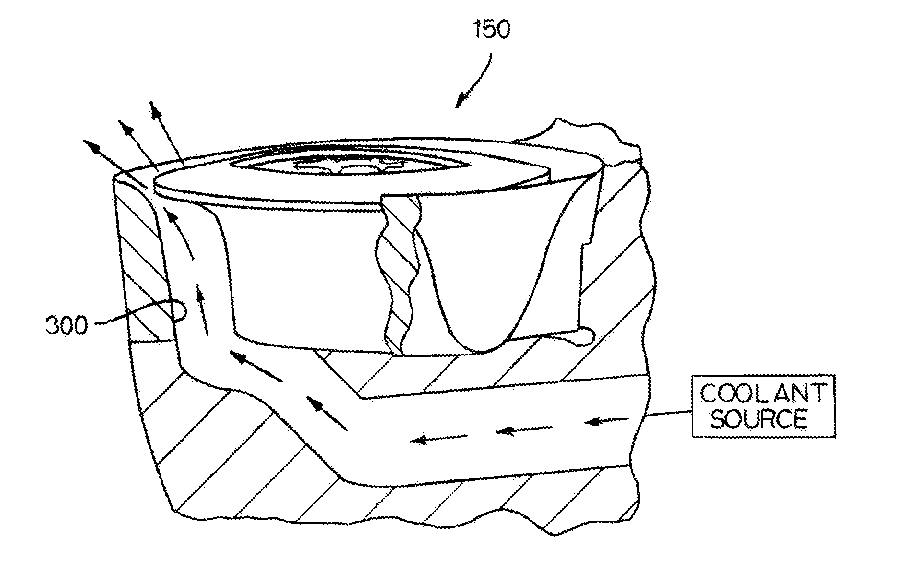
[0054]Referring to the drawings, there should be an appreciation that the cutting insert of the invention, as well as the cutting assembly of the invention, can operate in a number of different applications. The cutting insert, which has internal coolant delivery, is for use in the chipforming removal of material from a workpiece. In this respect, the cutting insert is for use in a chipforming material removal operation wherein there is enhanced delivery of coolant adjacent the interface between the cutting insert and the workpiece (i.e., the insert-chip interface) to diminish excessive heat at the insert-chip interface.

[0055]The enhanced delivery of coolant to the insert-chip interface leads to certain advantages. For example, enhanced delivery of coolant to the insert-chip interface results in enhanced lubrication at the insert-chip interface which decreases the tendency of the chip to stick to the cutting insert. Further, enhanced flow of coolant to the insert-chip interface lead...


PUM

PropertyMeasurementUnit
diversion anglesaaaaaaaaaa
angleaaaaaaaaaa

Abstract

A metalcutting insert that is useful in chipforming and material removal from a workpiece. The metalcutting insert includes a metalcutting insert body, which includes a cutting edge having at least one discrete cutting location. The metalcutting insert body further contains a distinct interior coolant passage communicating with the discrete cutting location. The distinct interior coolant passage has a coolant passage inlet defining a coolant passage inlet cross-sectional area, a coolant passage discharge defining a coolant passage discharge cross-sectional area, and an axial coolant passage length. The distinct interior coolant passage defines a coolant flow cross-sectional area along the axial coolant passage length thereof. The metalcutting insert further includes a plurality of surface features for enhancing coolant flow to the cutting edge.

Description

CLAIM TO PRIORITY[0001]This application is a continuation-in-part of application Ser. No. 12 / 797,249, filed on Jun. 9, 2010, which is a continuation-in-part of application Ser. No. 11 / 940,394, filed on Nov. 15, 2007, which is a continuation-in-part of application Ser. No. 11 / 654,833, filed on Jan. 18, 2007, the entire contents of which are incorporated herein by reference.BACKGROUND OF THE INVENTION[0002]The invention relates to a cutting insert, which has internal coolant delivery, and an assembly using the cutting insert for use in the chipforming removal of material from a workpiece. More specifically, the invention pertains to a cutting insert, as well as an assembly using the cutting insert, used for chipforming material removal operations wherein there is enhanced delivery of coolant adjacent the interface between the cutting insert and the workpiece (i.e., the insert-chip interface) to diminish excessive heat at the insert-chip interface.[0003]In a chipforming material remova...

Claims


Application Information

Patent Timeline
Patent Type & Authority Applications(United States)
IPC IPC(8): B23B27/10B23C5/28
CPCY10T407/23B23C2200/086B23B29/04B23Q11/1023B23B2200/086B23C2200/167Y10T407/14B23C5/20B23B2200/0461B23C5/06B23C5/28B23C2200/045B23B2200/168B23B27/10B23B27/141B23Q11/10
Inventor HOFFER, BRAD DANIELMULLER, THOMAS OWENLONG, II, THOMAS JERRY
Owner KENNAMETAL INC
Why Eureka
Try Eureka