Composite polishing pad

a polishing pad and composite technology, applied in the field of abrasive articles, can solve the problems of poor wiwnu film removal, difficult to achieve both these objectives at the same time, and difficult to achieve good wiwnu polishing

Inactive Publication Date: 2011-09-22
SCHWAPPACH KARL
View PDF0 Cites 13 Cited by
  • Summary
  • Abstract
  • Description
  • Claims
  • Application Information

AI Technical Summary

Problems solved by technology

It is difficult to achieve both these objective simultaneously because semiconductor wafers are often curved and warped.
These height variations and the wafer topography of the semiconductor wafer can interfere with the uniformity of the polishing process such that some regions of the wafer become over polished while other regions remain under polished.
Typically, hard (i.e., stiff) pads provide good planarization, but are associated with poor with-in wafer non-uniformity (WIWNU) film removal.
Soft (i.e., flexible) pads, on the other hand, provide polishing with good WIWNU, but poor planarization.
Nevertheless, this approach tends to degrade planarization performance when compared to u

Method used


Image

  • Composite polishing pad
  • Composite polishing pad
  • Composite polishing pad

Examples


Embodiment Construction

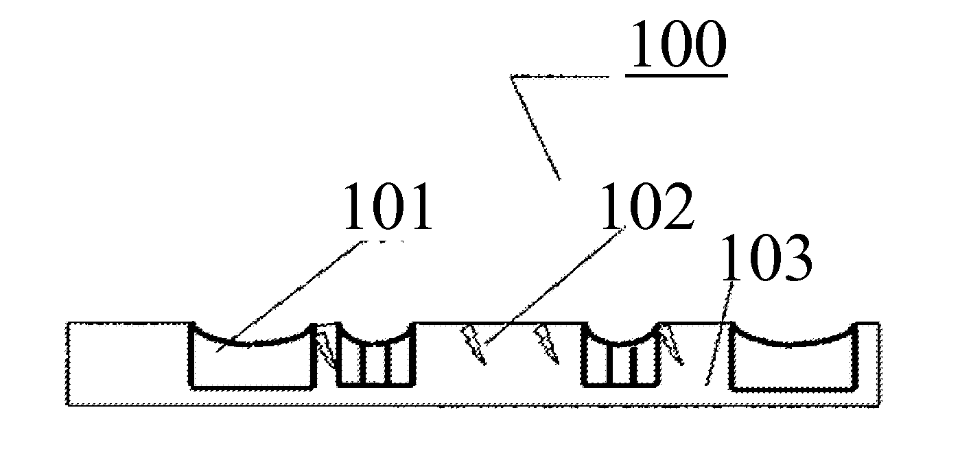
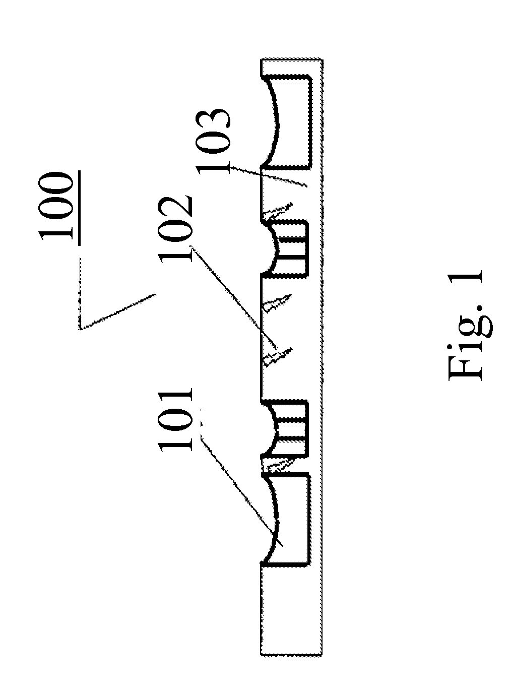
[0039]Described herein is a pad suitable in a variety of CMP processes. A plurality of independently suspended polishing pads 401 are assembled into a polishing article 400 referred to as composite polishing pad (CPP). Each polishing pad is suspended to a pressure pad 402 attached to a flexure 403 and subject to a substantially constant preload. The preload is applied through a stem end 406 referred to as dimple acting on the opposite side of the flexure suspending the polishing pad. Each polishing pad applies a substantially constant pressure via the stem independently of its location on the semiconductor wafer. The suspended polishing pad follows the contour of the semiconductor wafer regardless of the waviness of the semiconductor wafer. The preload apparatus is formed of a stem 406 attached to a spring mechanism 407 allowing substantially constant load as a function of vertical displacement. The ability of each polishing pad to comply in the plane of the wafer and follow the waf...


PUM


Abstract

An abrasive article referred to as composite polishing pad (CPP) includes a plurality of fixed abrasive elements or a plurality of chemical mechanical polishing (CMP) pads attached to a plurality of pressure pads suspended to flexible structures capable to follow the wafer topography. A plurality of stems with dimpled ends act on the pressure pads to generate desired pressure acting on the wafer. The stems are attached to a spring arrangement capable of substantial vertical deflection under a desired load. In one embodiment a plurality of pressure pads suspended to a plurality of stems by revolute joints. The stems are attached to a spring arrangement capable of substantial vertical deflection under a desired load. In another embodiment, a plurality of pressure pads are attached to a plurality of stems suspended to a series of springs capable of substantial vertical deflection under a desired load.

Description

CROSS-REFERENCE TO RELATED APPLICATIONS[0001]This application claims the benefits of the filing date of U.S. Provisional Patent Application Ser. No. 61 / 315,191 filed Mar. 18, 2010, which is entitled “Composite Polishing Pad”, U.S. Provisional Patent Application Ser. No. 61 / 315,210 filed Mar. 18, 2010, which is entitled “Method to enhance polishing performance of abrasive charged structured polymer substrates” and U.S. Provisional Patent Application Ser. No. 61 / 315,237 filed Mar. 18, 2010, which is entitled “Method to enhance polishing performance of abrasive charged polymer substrates” all of which are hereby incorporated herein in their entirety by reference.FIELD OF THE INVENTION[0002]The present invention is directed to an abrasive article including a plurality of abrasive element independently attached to gimbal structures.BACKGROUND OF THE INVENTION[0003]The invention relates to modifying the rigid substrate of a fixed abrasive article or a chemical mechanical pad used in semic...

Claims


Application Information

Patent Timeline
IPC IPC(8): B24D11/00
CPCB24B37/22B24B37/26B24B37/245
Inventor BOUTAGHOU, ZINE-EDDINE
Owner SCHWAPPACH KARL
Why Eureka
Try Eureka