

Mobile station
a mobile station and station technology, applied in the field of mobile stations, can solve the problems of downlink data lost without reaching the mobile station u
- Summary
- Abstract
- Description
- Claims
- Application Information
AI Technical Summary
Benefits of technology
Problems solved by technology
Method used
Image

Examples
first embodiment
(Mobile communication system according to the present invention)
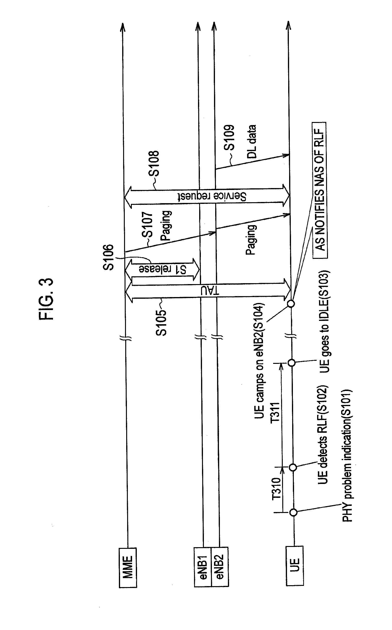
[0030]With reference to FIG. 1 through FIG. 4, a mobile communication system according to a first embodiment of the present invention will be explained.
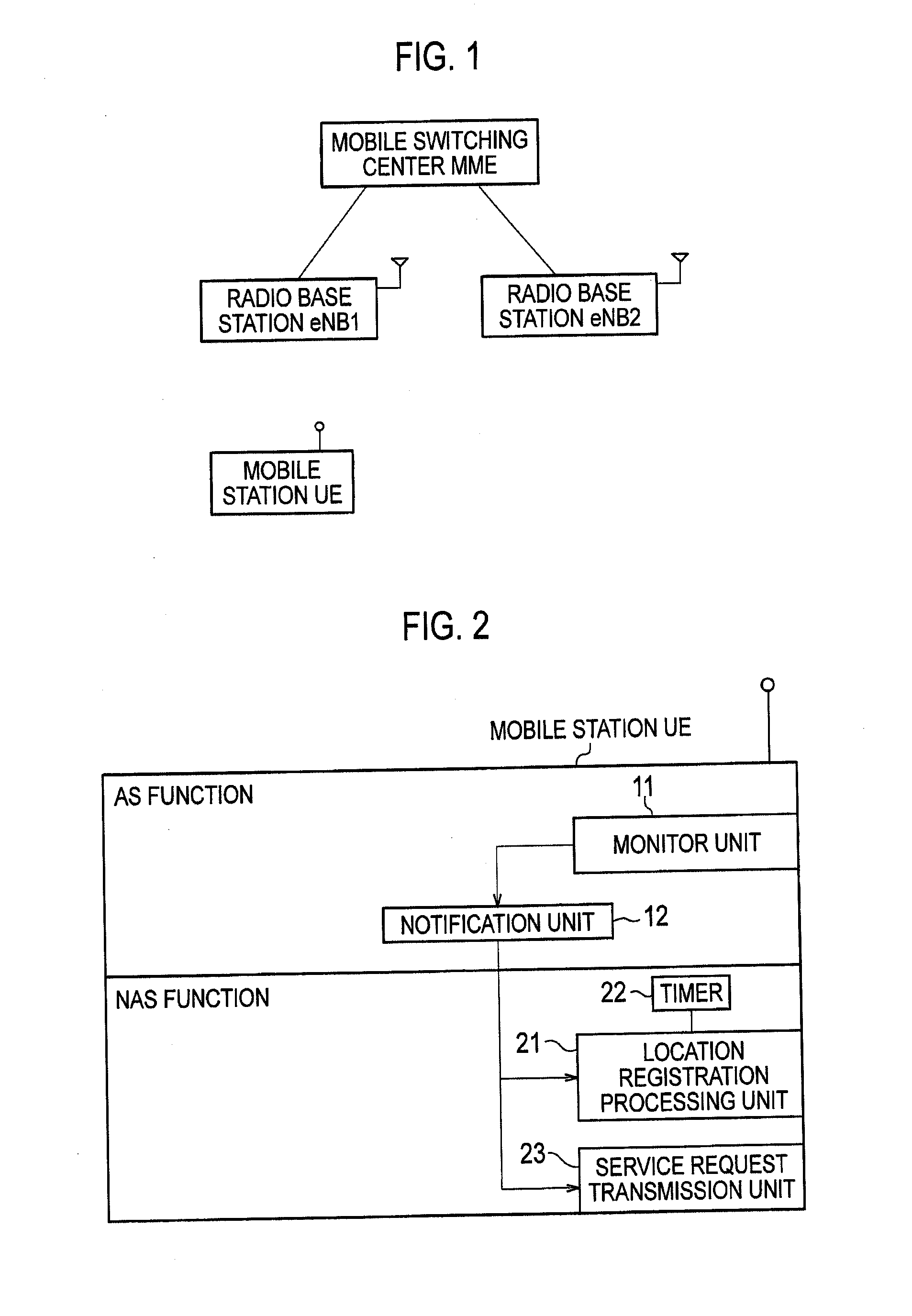
[0031]As illustrated in FIG. 1, the mobile communication system according to the embodiment is a mobile communication system of the LTE scheme, and includes : a mobile switching center MME; a radio base station eNB1 / eNB2; and a mobile station UE.
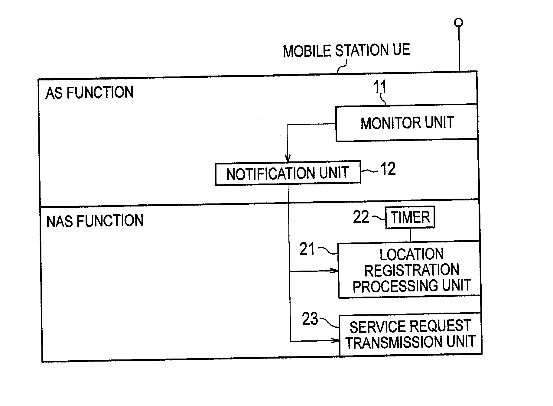
[0032]As illustrated in FIG. 2, the mobile station UE according to the embodiment includes: an AS function (first protocol function) corresponding to an AS (first protocol) terminated between the mobile station UE and the radio base station eNB; and an NAS function (second protocol function) corresponding to an NAS (second protocol) terminated between the mobile station UE and the mobile switching center MME.
[0033]The AS function includes a monitor unit 11 and a notification unit 12.
[0034]The monitor unit 11 is configured to moni...
first modified example
(First Modified Example)
[0065]With reference to FIG. 5, a mobile communication system according to a first modified example of the present invention will be described while focusing on the difference in the mobile communication system according to the above-described first embodiment.
[0066]As illustrated in FIG. 5, the AS function of the mobile station UE includes the notification unit 12, a transmission unit 13, and a timer 14. In this case, the AS function is configured to transition to an idle state, after an elapse of a first predetermined period after the failure (RLF) in the radio link established with the radio base station eNB is detected.
[0067]The transmission unit 13 is configured to transmit the uplink data.
[0068]The notification unit 12 is configured to monitor a time at which the uplink data is transmitted by the transmission unit 13, and to notify, to the NAS function, the transmission time of the uplink data.
[0069]The notification unit 12 is configured to notify, afte...
second modified example
(Second Modified Example)
[0074]With reference to FIG. 6, a mobile communication system according to a second modified example of the present invention will be described while focusing on the difference in the mobile communication system according to the above-described first embodiment.
[0075]As illustrated in FIG. 6, the configuration of the mobile station UE according to the second modified example is identical to that of the mobile station UE according to the above-described first embodiment except that a communication state management unit 24 is provided as the NAS function.
[0076]The communication state management unit 24 is configured to manage a type of communications performed via each radio link. In this case, when the type of communications is managed, QoS of the communication may be managed, or information indicating whether the current service is a real time service may be managed.
[0077]The location registration processing unit 21 is configured to determine whether or not ...
PUM
 Abstract
Description
Claims
Application Information