Al technical title is built by PatSnap Al team. It summarizes the technical point description of the patent document.
a technology which is applied in the field of applicator and clip, can solve the problems of time-consuming and expensive procedures, requiring as much as an hour of physician's or nurse's time, and uncomfortable for patients, and achieves the effect of facilitating hemostasis
Inactive Publication Date: 2011-09-22
INTEGRATED VASCULAR SYST
View PDF100 Cites 35 Cited by
Summary
Abstract
Description
Claims
Application Information
AI Technical Summary
This helps you quickly interpret patents by identifying the three key elements:
Problems solved by technology
Method used
Benefits of technology
[0075]Generally, an embodiment of a closure element in accordance with the present can include a clip for closing an opening formed in a wall of a body lumen or body tissue. Such a clip can include a shape-memory clip having a relaxed configuration with a substantially planar-annular body defining a lumen with a plurality of tines directed inwardly from the body. Additionally, the clip can be oriented and held by a clip applier in a retaining configuration having a substantially asymmetrically-elongated tubular shape with a substantially trapezoidal longitudinal cross-sectional profile and a proximal portion having the plurality of tines being longitudinally and distally directed with a first tine of the plurality being more distally oriented compared to a substantially opposite second tine being more proximal. Also, the clip can be capable of retracting to a deploying configuration having a substantially symmetrical tubular shape with a substantially rectangular longitudinal cross-sectional profile with the first tine being substantially even with th
Problems solved by technology
This procedure, however, may be time consuming and expensive, requiring as much as an hour of a physician's or nurse's time.
It is also uncomfortable for the patient, and requires that the patient remain immobilized in the operating room, catheter lab, or holding a
Method used
Image
Click on the blue label to locate the original text in one second.
Reading with bidirectional positioning of images and text.
Examples
Embodiment Construction
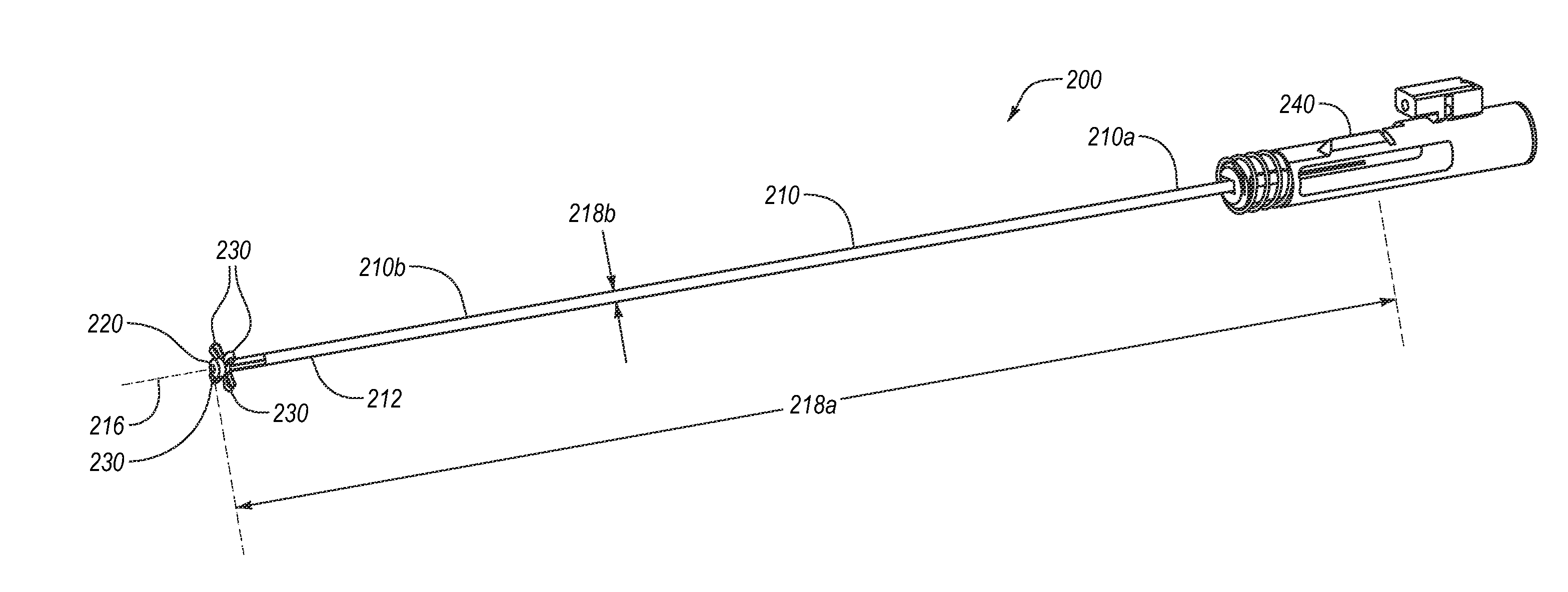
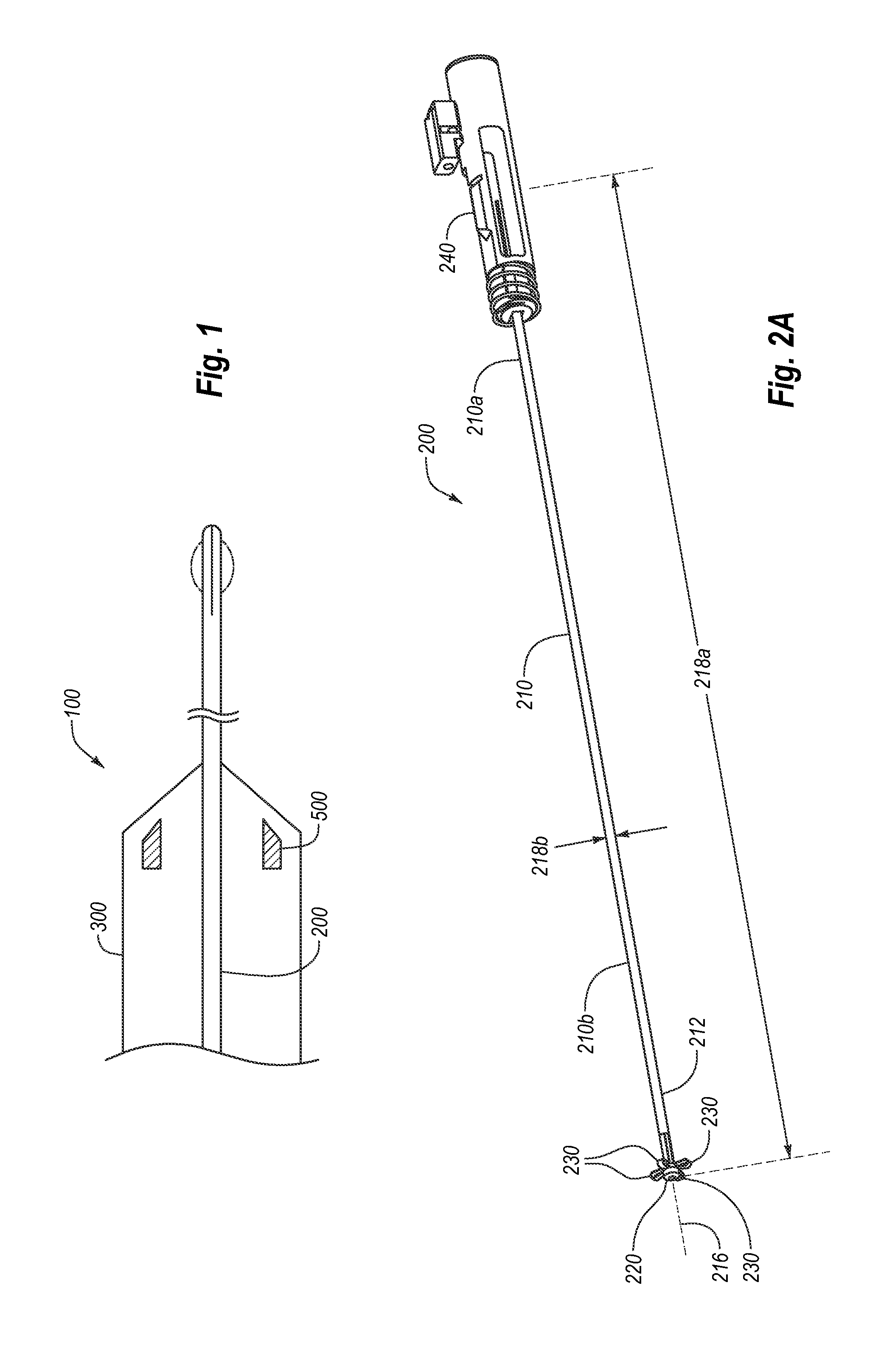
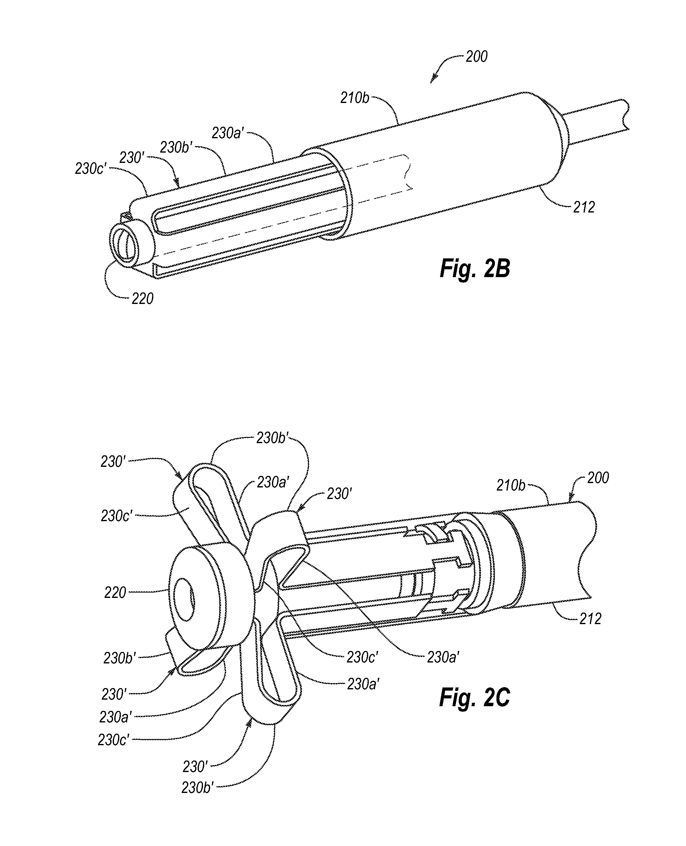
[0266]The embodiments described herein extend to methods, systems, and apparatus for managing access through tissue. Some of the apparatuses of the present invention are configured to deliver a device for managing access through tissue into an opening formed in and / or adjacent to tissue. Embodiments are additionally directed to an apparatus and method for delivering a closure element through tissue and into an opening formed in, or adjacent to, a wall of a blood vessel or other body lumen of any size.
[0267]The apparatus can be configured to receive and retain the closure element such that the closure element is disposed substantially within the apparatus. Thereby, if the apparatus is introduced via an introducer sheath, for example, the closure element can be disposed within, and delivered by way of, a lumen of the introducer sheath. The apparatus also is configured to engage the blood vessel wall adjacent to the opening and to position the closure element substantially adjacent to ...
PUM
Abstract
An apparatus for delivering a closure element can include a splittable carrier tube and a splitter to split the tube. The carrier tube can have an outer surface retaining a closure element in a tubular configuration and can be split into radially-expandable flaps. A closure element can have a shape-memory body having a relaxed configuration with a planar-annular body defining a lumen with tines directed inwardly from the body. The clip can be held in a retaining configuration having a substantially asymmetrically-elongated tubular shape with a trapezoidal longitudinal cross-sectional profile and a proximal end having the tines being longitudinally directed with a first tine being more distally oriented compared to a substantially opposite second tine being more proximal, and retracting to a deploying configuration having a tubular shape with a rectangular longitudinal cross-sectional profile with the first tine being even with the second tine when being delivered.
Description
CROSS-REFERENCE TO RELATED APPLICATIONS[0001]This application is a continuation-in-part of U.S. patent application Ser. No. 12 / 973,204, filed Dec. 20, 2010, which is a divisional of U.S. patent application Ser. No. 11 / 048,503, filed Feb. 1, 2005, now U.S. Pat. No. 7,857,828, which is a continuation-in-part of U.S. patent application Ser. No. 10 / 638,115, filed Aug. 8, 2003, now U.S. Pat. No. 7,867,249, which is a continuation-in-part of U.S. patent application Ser. No. 10 / 356,214, filed Jan. 30, 2003, each of which are incorporated herein by specific reference in its entirety. This application is also a continuation-in-part of U.S. patent application Ser. No. 11 / 852,190, filed on Sep. 7, 2007, which claims benefit of U.S. Provisional Application Ser. No. 60 / 843,325, filed Sep. 8, 2006, each of which are incorporated herein by specific reference in its entirety. This application is also a continuation-in-part of U.S. patent application Ser. No. 12 / 143,020, filed Jun. 20, 2008, which c...
Claims
Application Information
Patent Timeline
Application Date:The date an application was filed.
Publication Date:The date a patent or application was officially published.
First Publication Date:The earliest publication date of a patent with the same application number.
Issue Date:Publication date of the patent grant document.
PCT Entry Date:The Entry date of PCT National Phase.
Estimated Expiry Date:The statutory expiry date of a patent right according to the Patent Law, and it is the longest term of protection that the patent right can achieve without the termination of the patent right due to other reasons(Term extension factor has been taken into account ).
Invalid Date:Actual expiry date is based on effective date or publication date of legal transaction data of invalid patent.
Inventor PALERMO, THOMAS J.BELEF, WILLIAM M.CARLEY, MICHAEL T.GINN, RICHARD S.PANTAGES, ANTHONY J.JABBA, RONALD J.ELLINGWOOD, BRIAN A.VOSS, LAVEILLE KAOMCCRYSTLE, KELLY J.GROSS, T. DANIELKOKISH, ARKADY