Method and apparatus for backing the insde teeth of a sliding sleeve produced by way of powder metallurgy for a manual transmission

a technology of powder metallurgy and sliding sleeves, which is applied in the direction of gear teeth, metal rolling arrangements, applications, etc., can solve the problems of not being able to fabricate backings meeting higher requirements by means of rolling tools, and requiring expensive finishing treatment, so as to ensure the required dimensional stability and accelerate the treatment process accordingly.

Inactive Publication Date: 2011-09-29
MIBA SINTER AUSTRIA
View PDF16 Cites 1 Cited by
  • Summary
  • Abstract
  • Description
  • Claims
  • Application Information

AI Technical Summary

Benefits of technology

[0007]For carrying out such a method, a usual apparatus for backing the inside teeth of a sliding sleeve produced by way of powder metallurgy for a manual transmission having a rolling tool profiled according to the backing can be taken as the starting point if the rolling tool has a profile section adjoining the profile shape for the backing, which corresponds to the final form of the front-side tooth sections of the inside teeth delimited by the backings. In this case, not only the backing is rolled into the tooth head but at the same time, the front-side tooth section separated from the remaining tooth by the backing is treated so that no accumulations of material caused by a local delimitation of the rolling tool can be obtained along this tooth section. In addition, the profile shape of the rolling tool extending over the entire front-side tooth section including the backing brings about a calibrating of these tooth regions which

Problems solved by technology

For reasons of cost such backings of the inner teeth of sliding sleeves for manual transmissions are frequently fabricated by back rolling accompanied by a plastic displacement of material from the backing region, in which case undesired geometrical deformations and burr formations in the

Method used


Image

  • Method and apparatus for backing the insde teeth of a sliding sleeve produced by way of powder metallurgy for a manual transmission
  • Method and apparatus for backing the insde teeth of a sliding sleeve produced by way of powder metallurgy for a manual transmission
  • Method and apparatus for backing the insde teeth of a sliding sleeve produced by way of powder metallurgy for a manual transmission

Examples


Embodiment Construction

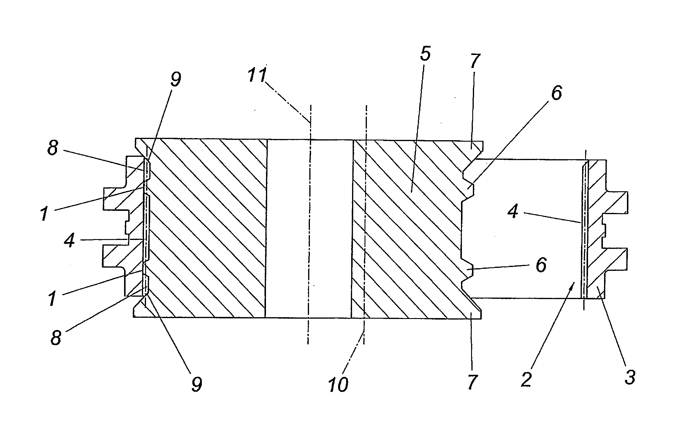
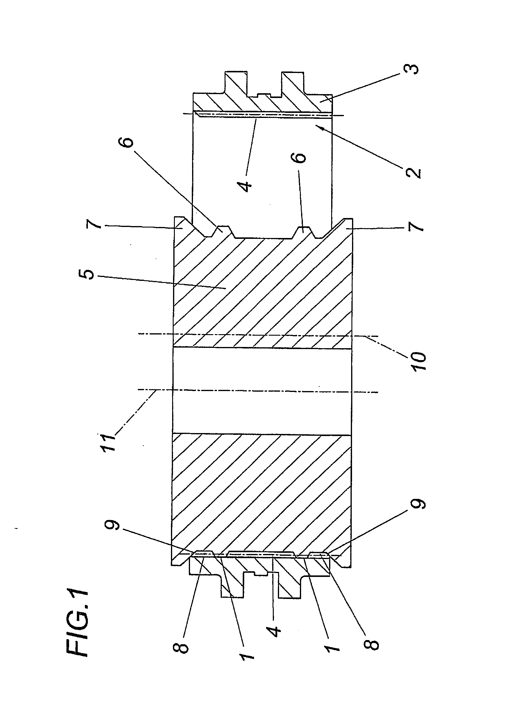
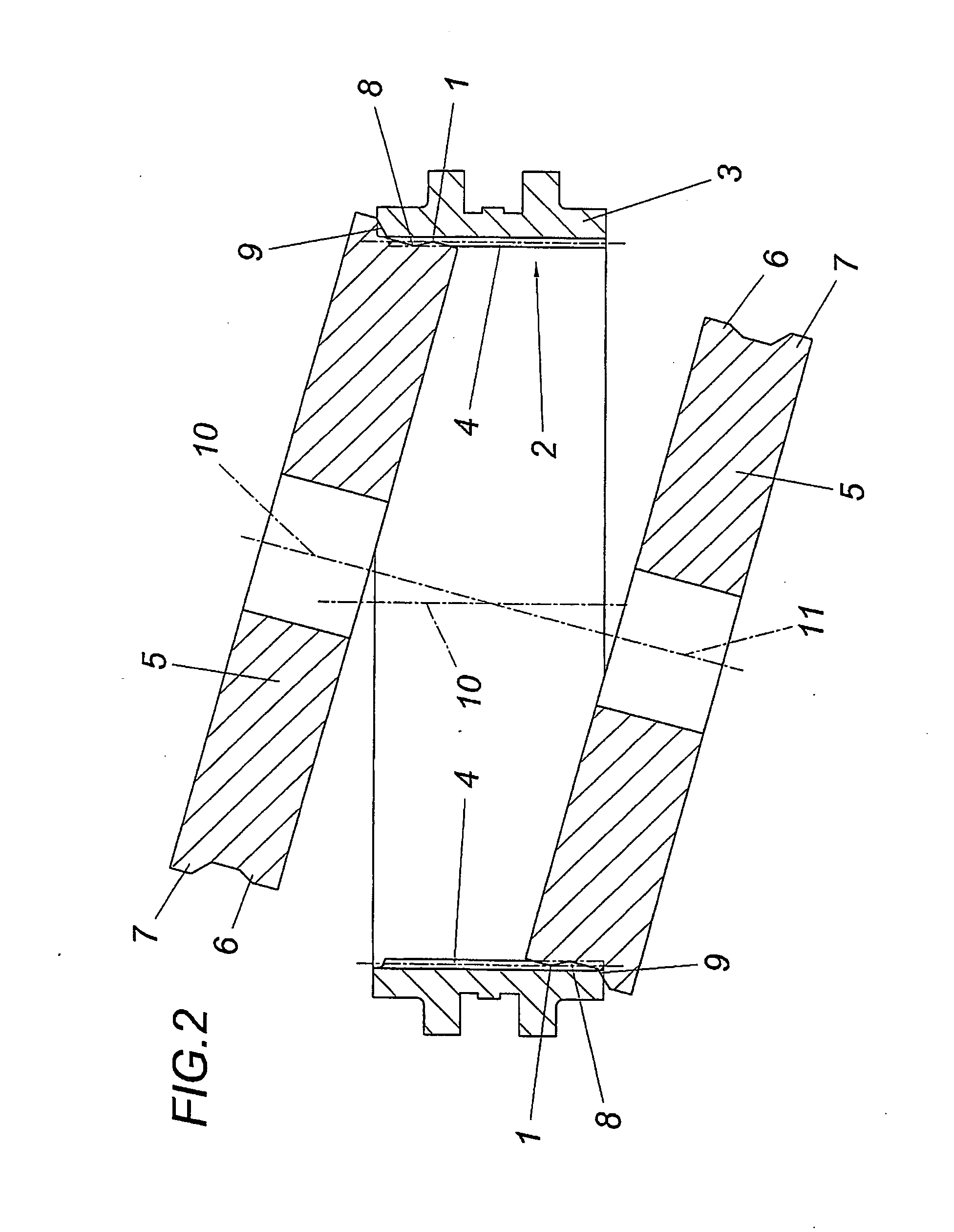
[0012]The inside teeth 2 of a sliding sleeve 3 to be produced with backings 1 for a conventional manual transmission, for example, of a motor vehicle, are formed in the sliding sleeve 3, which is produced by a corresponding sintering of a compression-moulded iron material by way of powder metallurgy, by axially continuous teeth 4 over the sleeve width, which according to the exemplary embodiment shown have a preform for a subsequent pitch on a front side, but otherwise have axially parallel flanks and an axially parallel head. In order to be able to back roll the backings 1 by means of a rolling tool 5 through a plastic displacement of material, the profile tool has a profile shape adapted to the end shape of the teeth 4, having a profile 6 which determines the backings 1 and an adjoining front-side profile section 7, which corresponds to the outline shape of the front-side tooth section 8 separated from the remaining tooth by the backing 1 and therefore at least calibrates if not s...


PUM

PropertyMeasurementUnit
Angleaaaaaaaaaa

Abstract

A method for backing the inside teeth (2) of a sliding sleeve (3) produced by way of powder metallurgy for a manual transmission is described where the backings (1) of the teeth (4) forming the front-side pitches (9) are formed with the aid of a rolling tool (5) by back rolling accompanied by plastic deformation of material from the backing region. In order to prevent burr formation, it is proposed that the front-side tooth sections (8) delimited by the backings (1) are simultaneously calibrated whilst forming and/or calibrating the relevant pitches (9) with the aid of the rolling tool (5) for forming the backings (1).

Description

FIELD OF THE INVENTION [0001]The invention relates to a method for backing the inside teeth of a sliding sleeve produced by way of powder metallurgy for a manual transmission, where the backings of the teeth forming the front-side pitches are formed with the aid of a rolling tool by back-rolling accompanied by plastic displacement of material from the backing region.DESCRIPTION OF THE PRIOR ART [0002]Recesses in the region of the tooth flanks of the inner teeth of annular components are designated as backing if they cannot be produced with tool delivery axially parallel to the ring axis but require setting of the tool onto the workpiece radially outwards. For reasons of cost such backings of the inner teeth of sliding sleeves for manual transmissions are frequently fabricated by back rolling accompanied by a plastic displacement of material from the backing region, in which case undesired geometrical deformations and burr formations in the tooth region cannot be avoided so that an e...

Claims


Application Information

Patent Timeline
IPC IPC(8): B21H5/02B21K1/30
CPCB21H5/022Y10T29/49471B21K1/30B23F5/163
Inventor MUELLER, ALEXANDERPAMMINGER, HELMUT
Owner MIBA SINTER AUSTRIA
Why Eureka
Try Eureka