Heating media regenerators for high efficiency driers

a technology of heat recovery and drier, which is applied in the direction of drying machines, lighting and heating apparatus, furnaces, etc., can solve the problems of reducing the efficiency of all types of conventional driers, reducing the efficiency of conventional driers, so as to achieve uniform and consistent drying of materials, reduce the effect of outside energy input and special effect of drying material

Inactive Publication Date: 2011-09-29
SHIVVERS GRP INC THE AN IOWA
View PDF0 Cites 14 Cited by
  • Summary
  • Abstract
  • Description
  • Claims
  • Application Information

AI Technical Summary

Problems solved by technology

While the grain industry is not the only industry that requires significant drying, it is indicative of the problems that exist.
In reality, the grain also takes on sensible heat and raises in temperature during the process, the flow of heating gas is not uniform, the grain is often heated more on one side of the dryer than the other, etc., such that the efficiency of all types of conventional driers is comparatively low.
Further, there are many other solids, semi-solids and initially liquid compositions that are dried each year by vaporizing a liquid component or completely evaporating most or all of an incoming stream, at considerable costs in terms of fuel, energy and undesired emissions due to combustion of the fuels.
For example, grain kernels can be cracked by cooling or heating too quickly, which can lead to degradation of the grain.
While conventional driers may provide a chosen average moisture content, the content may not be consistent.
Consequently, problems are encountered in many types of conventional cross flow grain driers where, the grain is heated and dried by air passing perpendicularly to the flow of the grain.
In such driers, the grain on one side of the dryer that first encounters the heated air is overly dried and may be dried too quickly so as to cause cracking and the grain on the opposite or on the air discharge side tends to be too wet.

Method used


Image

  • Heating media regenerators for high efficiency driers
  • Heating media regenerators for high efficiency driers
  • Heating media regenerators for high efficiency driers

Examples


Embodiment Construction

[0044]As required, detailed embodiments of the present invention are disclosed herein; however, it is to be understood that the disclosed embodiments are merely exemplary of the invention, which may be embodied in various forms. Therefore, specific structural and functional details disclosed herein are not to be interpreted as limiting, but merely as a basis for the claims and as a representative basis for teaching one skilled in the art to variously employ the present invention in virtually any appropriately detailed structure.

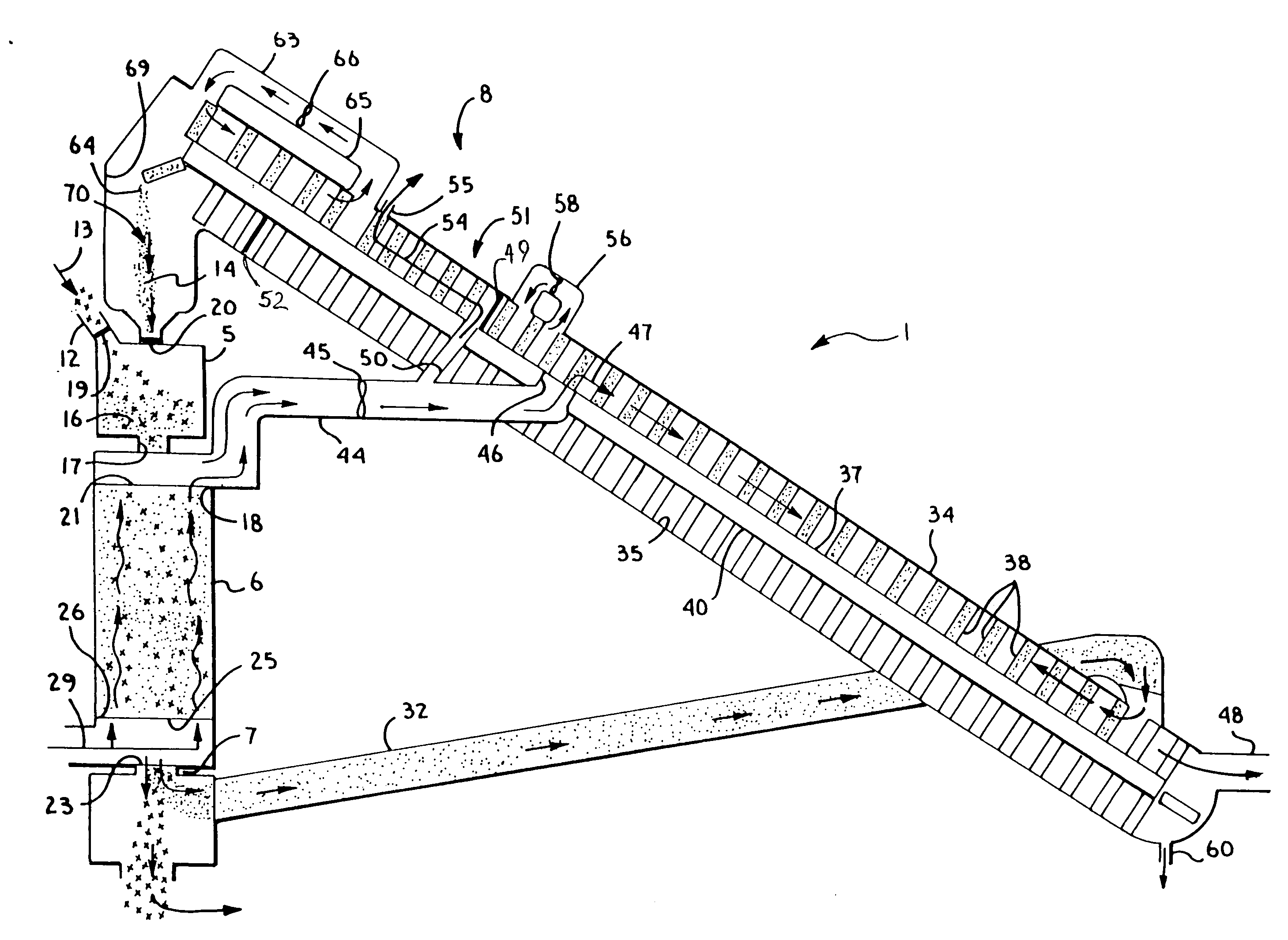
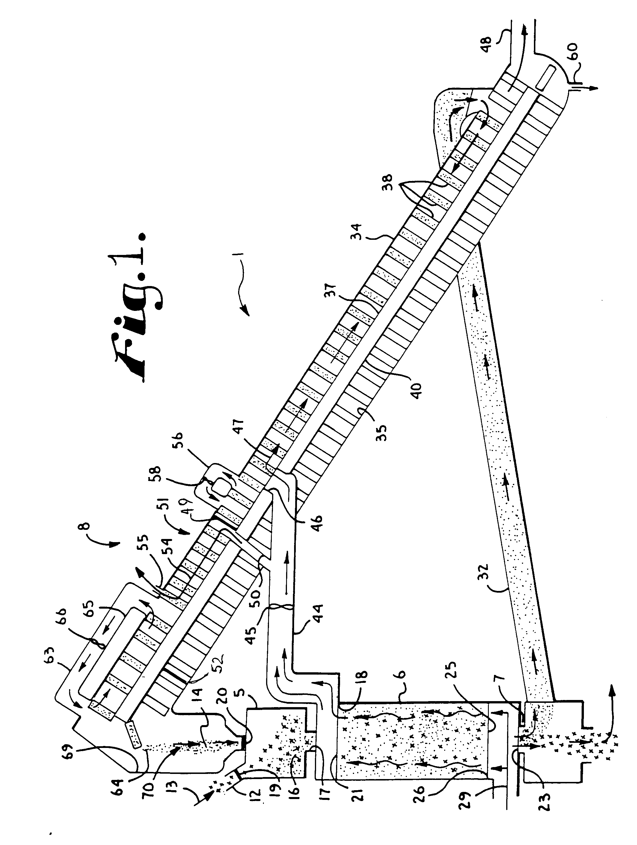
[0045]As shown in FIG. 1, the reference numeral 1 generally represents a drier in accordance with the present invention.

[0046]The drier comprises an inlet mixer 5 (that also functions to provide a heating zone or sweatbox), a drying chamber 6, a separator 7 and a regenerator system 8.

[0047]A material 12 to be dried (here corn) is fed at the arrow numbered 13 into the mixer 5 from a source outside the drier 1. At the same time a media 14 (here smooth rock of a...


PUM


Abstract

A drier apparatus for removing water from various materials includes a mixer, drying chamber, separator and regenerator and a method for use of the apparatus. The material to be dried is mixed with a heated media to form a mixture which then passes through the chamber. While passing through the chamber, a comparatively cool fluid is passed generally counter current through the mixture so that the mixture becomes cooler and drier and the fluid becomes hotter and more saturated with moisture. The mixture is then separated into drier material and media. The media is transferred to the regenerator and heated therein by the hot fluid from the chamber and supplemental heat is supplied to bring the media to a preselected temperature for mixing with incoming material to be dried. In a closed loop embodiment of the apparatus, the fluid exiting the regenerator is also recycled from the regenerator to the chamber and a chiller is utilized to reduce the temperature of the fluid to a preselected temperature and / or a preselected dew point temperature.

Description

CROSS REFERENCE TO RELATED APPLICATIONS[0001]This application claims the benefit of U.S. Provisional application No. 60 / 834,125 filed Jul. 28, 2006 and U.S. Provisional application No. 60 / 899,964 filed Feb. 7, 2007 which are incorporated herein by reference.STATEMENT REGARDING UNITED STATES GOVERNMENT SPONSORED RESEARCH OR DEVELOPMENT[0002]The present invention was at least in part made with support from the United States Government under Contract No. DE-FC36-01G011037 awarded by the Department of Energy and under Contract No. 2005-33610-15517 awarded by the USDA SBIR. The United States Government has certain rights in the invention.BACKGROUND OF THE INVENTION[0003]The present invention is directed to improvements in driers and methods of drying used to dry various materials, including newly harvested grain, wood pellets, etc. and, in particular, to driers that recover and utilize a comparatively high percentage of the energy used in the drying process.[0004]The drying industry is v...

Claims


Application Information

Patent Timeline
Patent Type & Authority Applications(United States)
IPC IPC(8): F26B3/02F26B21/10
CPCF26B3/205F26B2200/24F26B2200/06
Inventor SHIVVERS, STEVE D.
Owner SHIVVERS GRP INC THE AN IOWA
Why Eureka
Try Eureka