Method and device to remove fluid and vapor

Active Publication Date: 2011-09-29
SQI DIAGNOSTICS SYST
View PDF7 Cites 6 Cited by
  • Summary
  • Abstract
  • Description
  • Claims
  • Application Information

AI Technical Summary

Problems solved by technology

A major defect inherent in uncontrolled air drying involves the passage of the receding air-water interface through the specimen.
These techniques are inherently difficult to implement.
Another problem is positioning drying devices onto carrier substrates within confined spaces, to realiz

Method used


Image

  • Method and device to remove fluid and vapor
  • Method and device to remove fluid and vapor
  • Method and device to remove fluid and vapor

Examples


Embodiment Construction

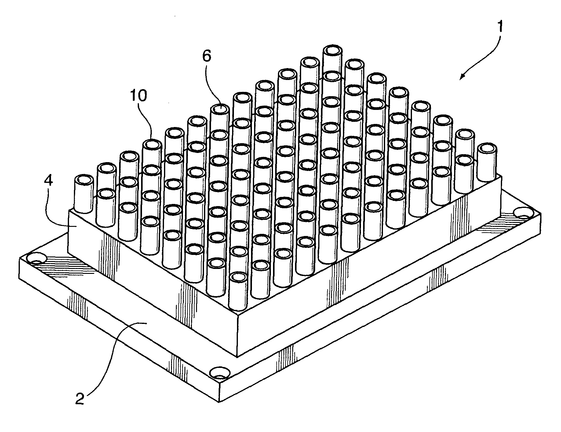
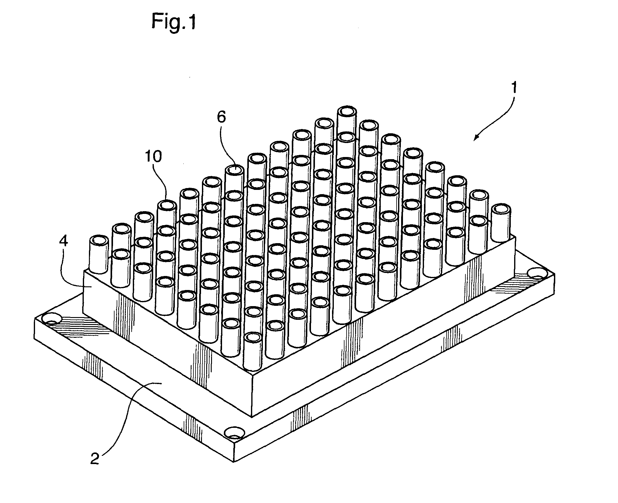
[0015]As shown in FIG. 1, drying apparatus 1 has a frame 2. The frame 2 is can be coupled

to an actuator (not shown) that moves the frame in three dimensions along an XYZ plane. The actuator functions as a displacement means and can be one of many actuators known in the art. A preferred actuator is ELx405 Microplate Washer, BioTek Instruments, U.S.A.

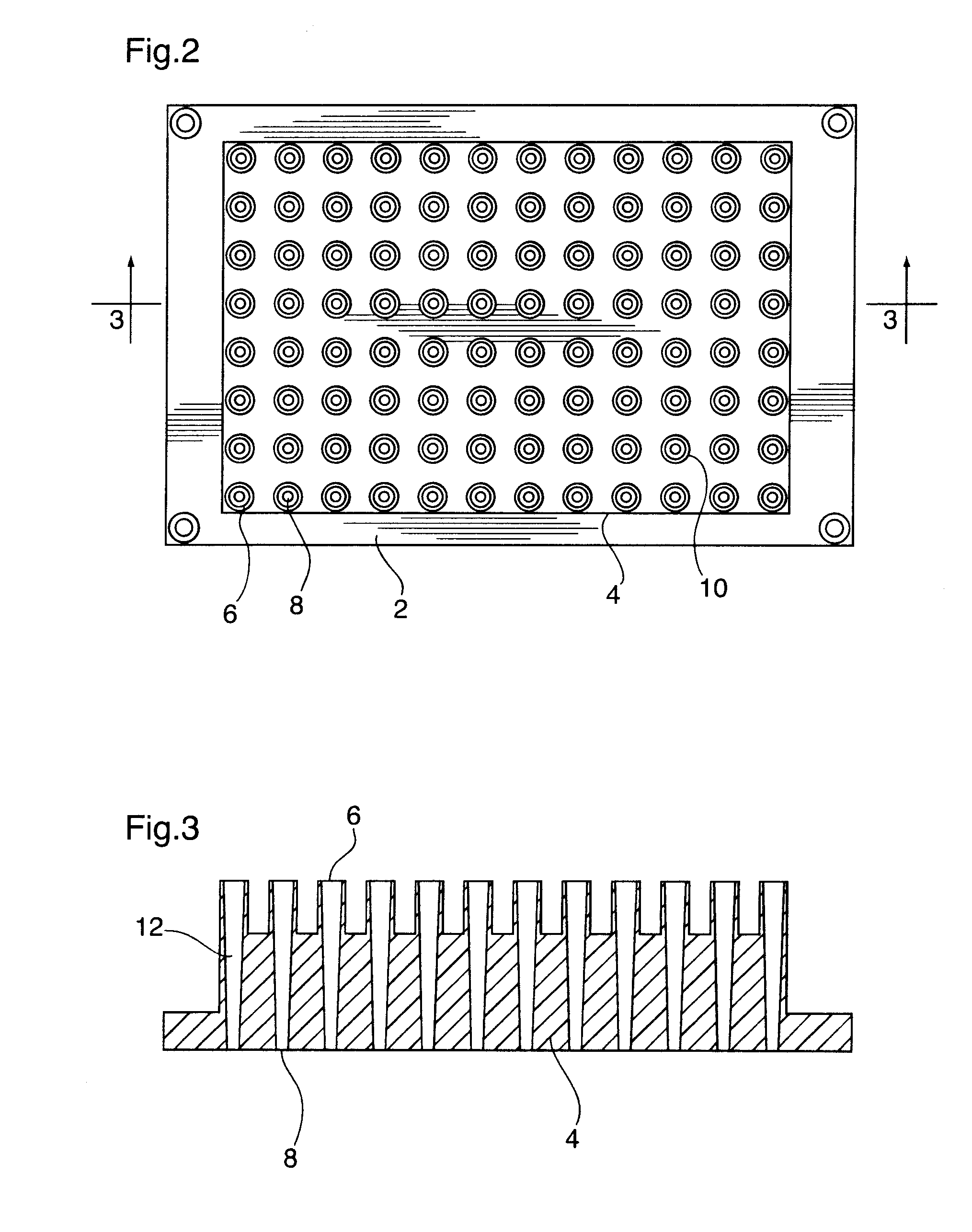
[0016]The drying apparatus includes a housing 4 that is attached to the frame 2. A plurality of aspiration tubes 10 is located in the housing. In alternate embodiments, the dryer can have as few as one tube. Each of the tubes 10 defines a length, and defines a longitudinal bore 12 along the length between a first open end 6 and a second open end 8. As shown in FIG. 3, the longitudinal bore 12 is preferably tapered wherein the first open end 6 has a greater diameter than the diameter of the second open end 8.

[0017]The length of the aspiration tube 10 may vary. In the preferred embodiment, the length is sufficient to maintain an aspect rati...


PUM


Abstract

The present invention relates to a method and device for the removal of fluids and vapors in containment, from adjacent surfaces including supporting flat surfaces and substrates, such as protein spots printed in arrays and micro-array formats. This method and device removes fluids and vapors under controlled and repeatable conditions, enabling uniform phases for degree of drying incurred by objects, specimen and structures, including tissues, adsorbed particles and biological substrates, while reducing and preventing impact of meniscus phase surface tension forces.

Description

FIELD OF THE INVENTION[0001]The present invention relates to a method and device for the removal of fluids and vapors from adjacent assay surfaces including supporting flat surfaces and substrates, such as protein spots printed in arrays and micro-array formats.DESCRIPTION OF THE RELATED ART[0002]Most soft structures, including biological materials and tissues will collapse, flatten or shrink when subjected to drying. A major defect inherent in uncontrolled air drying involves the passage of the receding air-water interface through the specimen. Throughout the lengthy air drying process, associated surface tension forces exert shear and stress up to approximately 2000 p.s.i (pounds per square inch). To prevent collapse and distortion and destruction of soft structures it is mandatory to modulate passage of the interface over surfaces and or through the structure to be dried. This can be accomplished to the level of nanostructure preservation using complex techniques, including freez...

Claims


Application Information

Patent Timeline
IPC IPC(8): F26B5/12A47L9/02
CPCB01J2219/00315B01J2219/00414G01N35/1074F26B5/04F26B5/12B01J2219/00605B01L2200/025B01L2400/049
Inventor LEA, PETER
Owner SQI DIAGNOSTICS SYST
Why Eureka
Try Eureka