
Battery test rig

Inactive Publication Date: 2011-09-29
ROBERT BOSCH GMBH
View PDF3 Cites 7 Cited by
  • Summary
  • Abstract
  • Description
  • Claims
  • Application Information

AI Technical Summary

Benefits of technology

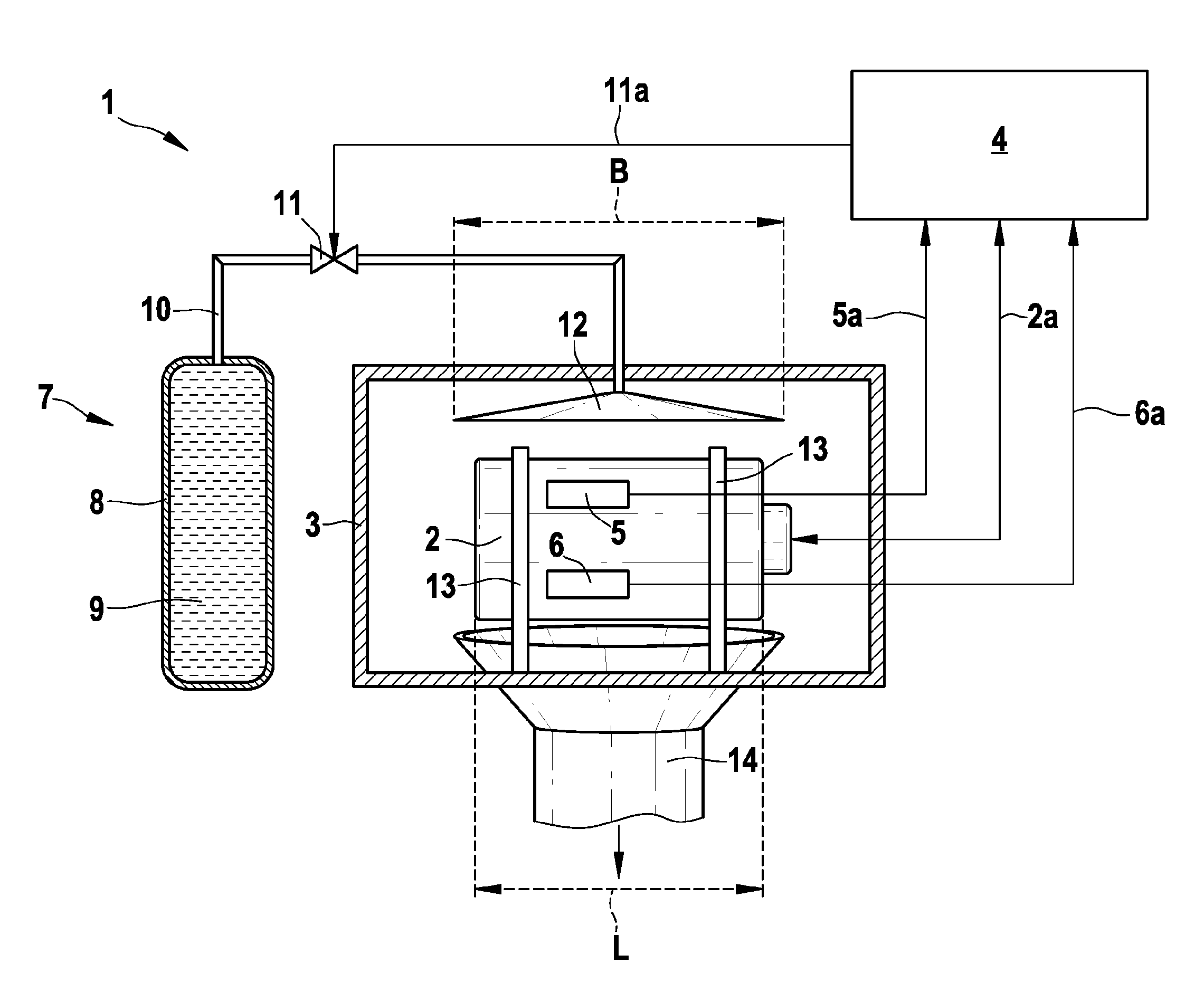
[0003]In contrast, the battery test rig according to the invention has the advantage that it is possible to test or examine batteries with an increased level of safety. According to the invention, high-efficiency cooling can be carried out in this case if necessary. This is achieved, according to the invention, by virtue of the fact that the battery test rig comprises a cooling apparatus which is connected to a regulation unit. A sensor device is connected to the regulation unit in order to monitor the battery. If the regulation unit detects that there is a hazard situation, it activates the cooling apparatus in order to cool the battery in order to thus prevent a critical battery state. The inventive external cooling of the battery thus makes it possible, on the one hand, to reduce a temperature of the battery and a pressure inside the battery, with the result that a critical situation can be avoided. The inventive use of the cooling apparatus also makes it possible to safely check research samples of batteries, in particular.
[0004]The cooling apparatus preferably comprises a pressure vessel which is connected to a test cell, in which the battery is arranged, via a line. The cooling apparatus also comprises a switching valve which is connected to the regulation unit and is opened in a hazard situation in order to lead a cooling medium stored in the pressure vessel to the battery. As a result, a large area of the battery may be wetted with the coolant, thus resulting in a high degree of cooling efficiency. The pressure vessel may also have a large supply of cooling medium in order to be able to cool the battery for as long as possible.
[0005]The cooling apparatus more preferably comprises a nozzle which is arranged in the test cell and makes it possible for the cooling medium to expand in the vicinity of the battery. In this case, the cooling medium is sprayed onto the battery via the nozzle in order to cool the battery over as large an area as possible. In this case, the nozzle is preferably arranged above the battery, such that the cooling medium flows down along the outer periphery of the battery. In this case, the battery is more preferably arranged horizontally in the test cell, with the result that as large an area as possible can be wetted with cooling medium.
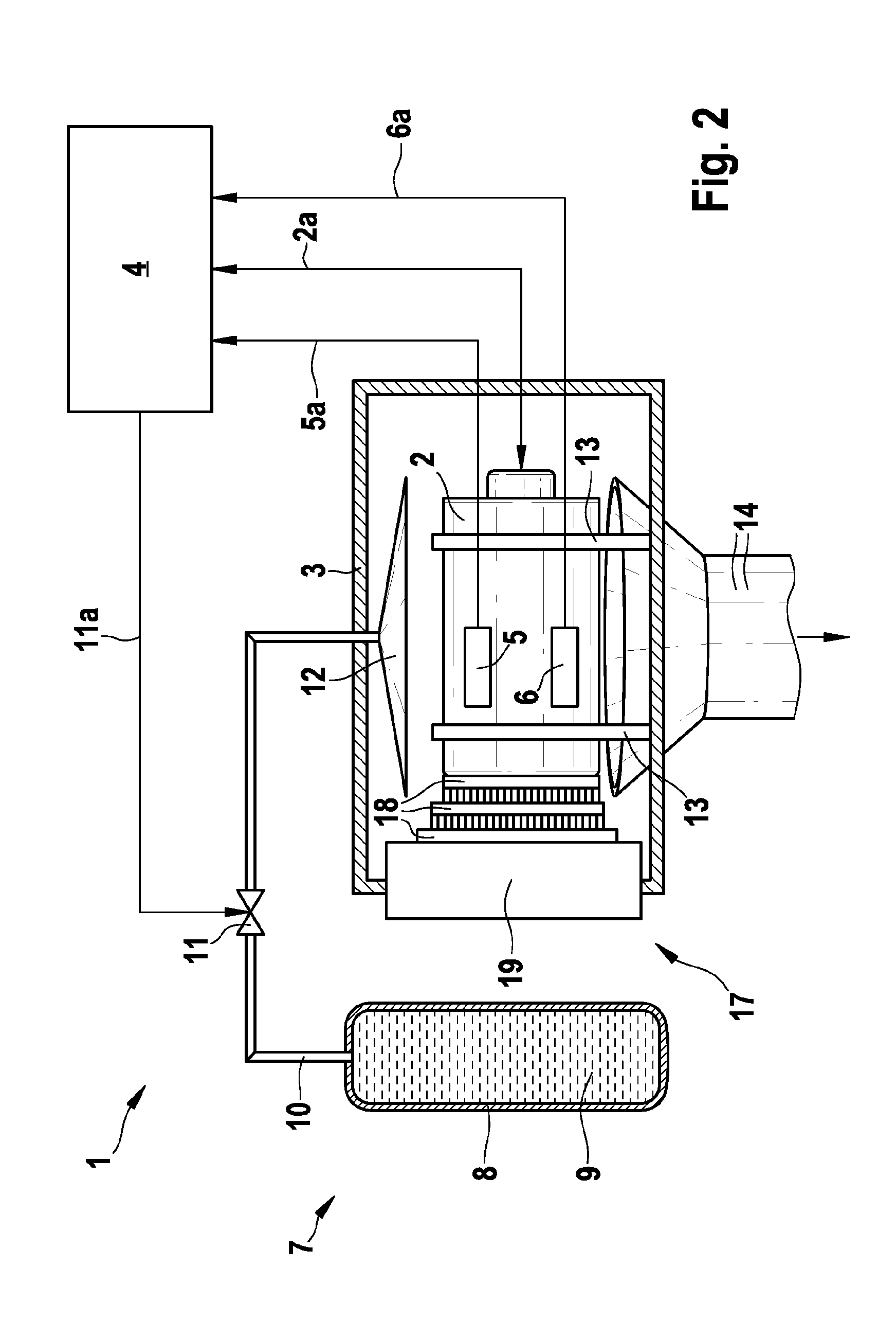
[0006]According to another preferred refinement of the present invention, the cooling apparatus comprises at least one Peltier unit which is arranged in the test center in order to cool the battery. The Peltier units consist of Peltier elements which are placed flat against one another, the Peltier elements consisting, for example, of two semiconductor ceramics which are connected by metal bridges. If a safety-critical state of the battery to be checked occurs, the Peltier unit is energized, as a result of which one of the semiconductor ceramics is cooled, whereas the other is heated. In this case, the cooling apparatus particularly preferably comprises a multiplicity of Peltier units which are arranged in the form of a pyramid. This makes it possible to achieve a plurality of cooling stages, such that even large temperature differences of up to 70 Kelvin and temperatures below 0° C. can be achieved. In this case, the last stage of the multiplicity of Peltier units is preferably connected to a heat exchanger which transports the waste heat from the test cell.
[0007]The sensor device preferably comprises a temperature sensor and / or a pressure sensor and / or a force sensor, in particular a strain gage, and / or a distance sensor. In this case, the sensors are preferably arranged on an outer side of the battery. As a result, a simple structure of the battery test rig is achieved and, in particular, a multiplicity of batteries can be checked in a short time. It is noted that a plurality of different sensors are particularly preferably arranged on the battery. Alternatively, it is naturally also possible to arrange a plurality of identical sensors on a battery to be examined.
[0008]The battery test rig preferably also comprises a suction apparatus in order to suction gases or other media from the interior of the test cell. On the one hand, this results in toxic gases, for example, being able to be safely suctioned from the test cell and, on the other hand, avoids a disproportionate pressure increase inside the test cell. A vacuum can also be generated in the test cell as a result.

Problems solved by technology

However, a considerable potential hazard may result in this case.
Furthermore, exothermic reactions may entail a further supply of heat.
Consequently, the battery may be destroyed by an explosion.
As a result, work on battery test rigs may be hazardous.

Method used


Image

  • Battery test rig
  • Battery test rig
  • Battery test rig

Examples


Embodiment Construction

[0014]A battery test rig 1 according to one preferred exemplary embodiment of the invention is described in detail below with reference to FIG. 1.

[0015]As can be seen from FIG. 1, the battery test rig 1 comprises a test cell 3 in which a battery 2 to be checked is arranged. In this case, the battery 2 is held in a holder 13 which comprises a plurality of narrow carriers. The use of the narrow carriers makes it possible, in particular, to avoid the test results being distorted by thermal loads. Furthermore, good accessibility to the battery 2 to be checked can be ensured.

[0016]The battery test rig 1 also comprises a regulation unit 4 and a cooling apparatus 7. A pressure sensor 5 and a temperature sensor 6 are also provided and are fixed to an outer side of the battery 2. The pressure sensor 5 and the temperature sensor 6 are connected to the regulation unit 4 via lines 5a and 6a. In this case, the reference symbol 2a denotes an electrical connection between the battery 2 and the reg...


PUM


Abstract

The present invention relates to a battery test rig, comprising a test cell (3) in which a battery (2) to be tested is arranged, a holder (13) which is arranged in the test cell (3) and is able to hold the battery (2), a regulation unit (4) which can be connected to a battery (2) arranged in the holder (13), at least one sensor device (5, 6) for monitoring the battery (2), wherein the sensor device (5, 6) is connected to the regulation unit (4), and a cooling apparatus (7), which is connected to the regulation unit (4) and is designed to cool the battery (2) in the test cell (3) from the outside in a hazard situation.

Description

BACKGROUND OF THE INVENTION[0001]The present invention relates to a battery test rig which is used to examine or check different batteries.[0002]The function and load limits of batteries are checked, for example, as part of development and production. However, a considerable potential hazard may result in this case. In particular, in the case of excessive charging or discharging or else in the case of other external environmental influences, for example a temperature increase, gaseous cleavage products, which may result in a pressure increase, may be produced in the event of reactions between the existing battery materials (cathode, anode, electrolyte). Furthermore, exothermic reactions may entail a further supply of heat. Consequently, the battery may be destroyed by an explosion. As a result, work on battery test rigs may be hazardous. It would therefore be desirable to have an improved level of safety, in particular, for the employees working with battery test rigs.SUMMARY OF THE...

Claims


Application Information

Patent Timeline
IPC IPC(8): F25B21/02
CPCH01M6/5083H01M10/5085H01M10/5004H01M10/4285H01M10/613H01M10/6572Y02E60/10
Inventor DALLINGER, FRANKSTEMMANN, JANNISKERN, RAINER
Owner ROBERT BOSCH GMBH
Learn More