Compact vapor chamber and heat-dissipating module having the same

a heat dissipating module and compact technology, applied in the direction of basic electric elements, semiconductor devices, lighting and heating apparatus, etc., can solve the problems of inability to meet the requirements of compact electronic products, inevitably affecting the performance of electronic components, etc., to facilitate the compact design of electronic products, increase the heat-conducting area, and quickly conduct heat.

Inactive Publication Date: 2011-09-29
CELSIA TECH TAIWAN INC
View PDF90 Cites 45 Cited by
  • Summary
  • Abstract
  • Description
  • Claims
  • Application Information

AI Technical Summary

Benefits of technology

[0013]According to the compact vapor chamber of the present invention, a recess is formed on the evaporating section and located to correspond to the electronic heat-generating element, and the recess is configured to receive a portion of the electronic heat-generating element therein and thermally contact the top surface of the electronic heat-generating element. Thus, the problem that a gap inevitably exits between the conventional vapor chamber and the electronic heat-generating element can be avoided. The compact vapor chamber of the present invention has a recess for receiving a portion of the electronic heat-generating element, so that the distance of the electronic heat-generating element protruding from the vapor chamber can be reduced, which facilitates the compact design of an electronic product.
[0014]According to the above, since the compact vapor chamber of the present invention has a recess located to correspond to the electronic heat-generating

Problems solved by technology

If the heat is not dissipated to the outside and accumulated in the electronic element, the temperature of the electronic element will rise to affect its performance and even su

Method used


Image

  • Compact vapor chamber and heat-dissipating module having the same
  • Compact vapor chamber and heat-dissipating module having the same
  • Compact vapor chamber and heat-dissipating module having the same

Examples


Embodiment Construction

[0022]The characteristics and technical contents of the present invention will be described with reference to the accompanying drawings. However, the drawings are illustrative only, but not used to limit the present invention.

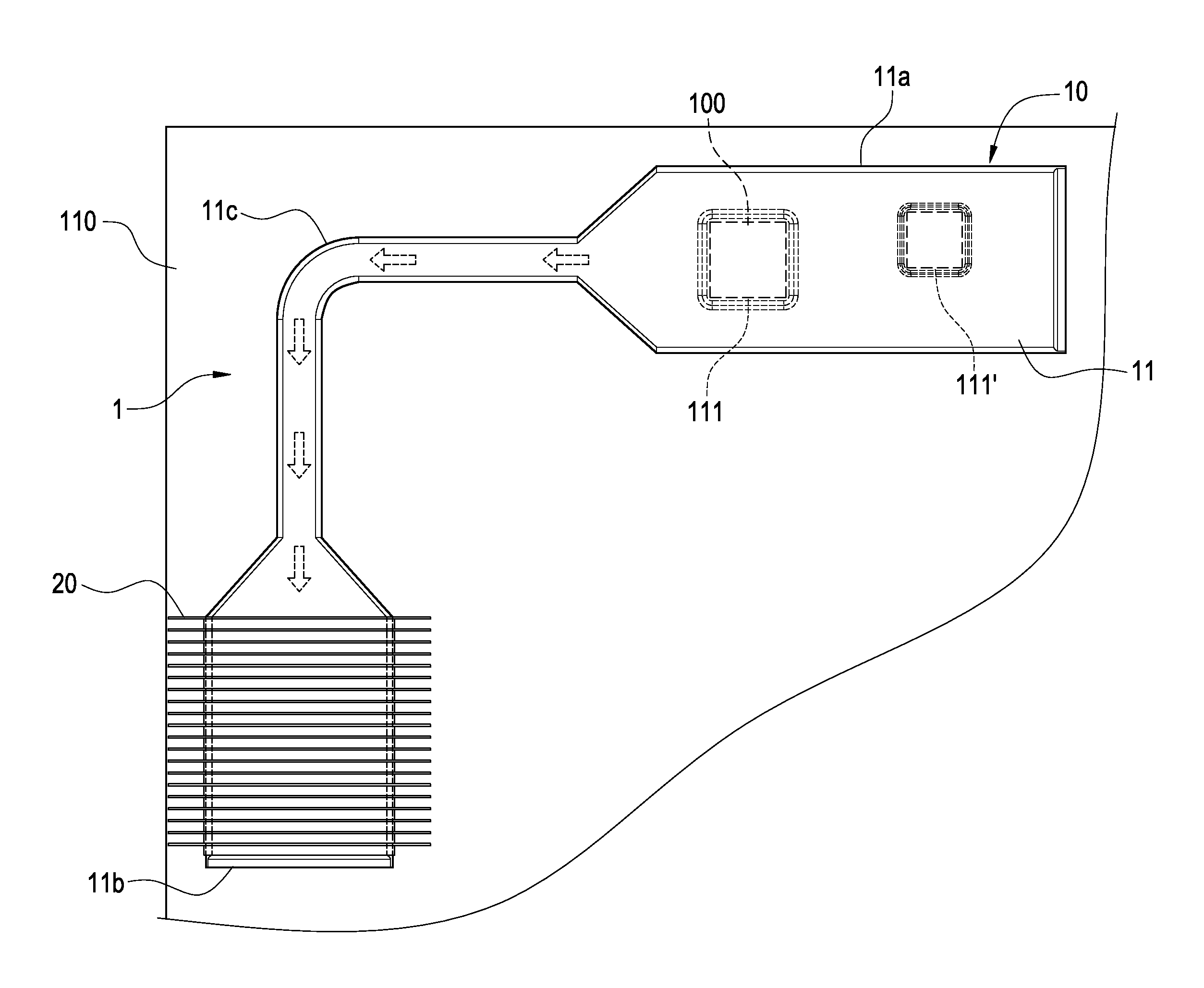
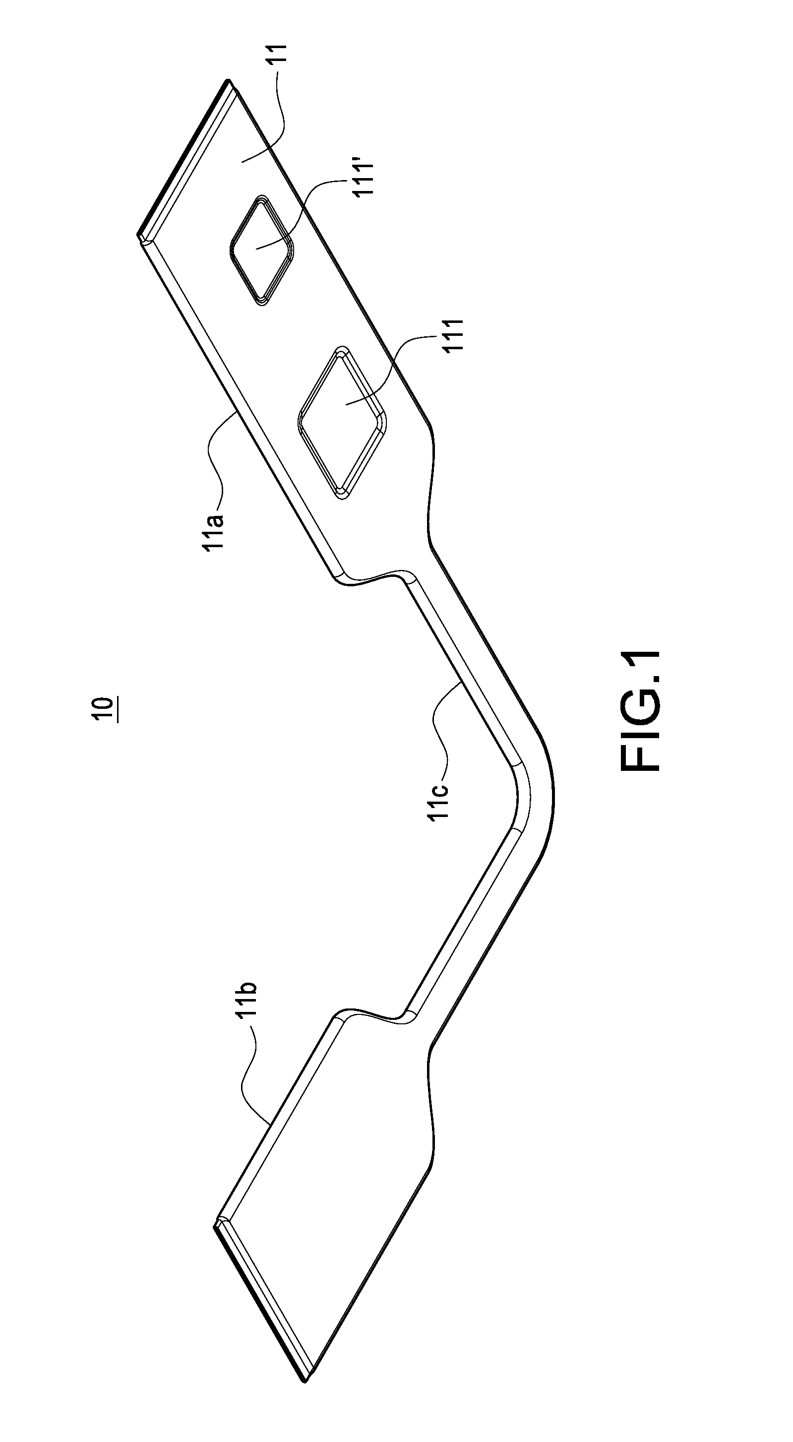
[0023]Please refer to FIGS. 1 to 4. The present invention provides a compact vapor chamber 10 (referred to as “vapor chamber 10” hereinafter) and a heat-dissipating module 1 having such a compact vapor chamber 10. The vapor chamber 10 is used to thermally conduct heat of an electronic heat-generating element 100, while the heat-dissipating module 1 is used to dissipate the heat of the electronic heat-generating element 100. The electronic heat-generating element 100 is electrically connected to a circuit board 110 (as shown in FIGS. 3 and 4).

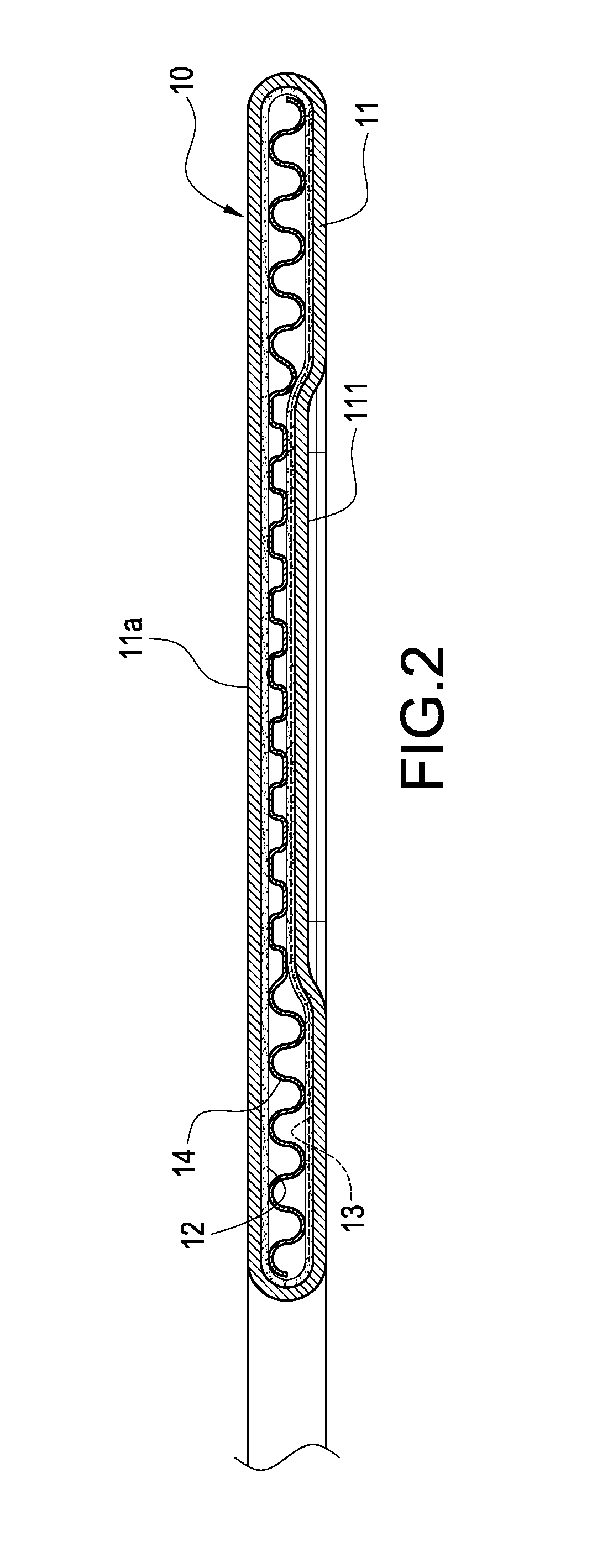
[0024]As shown in FIG. 2, the vapor chamber 10 is constituted of a flat sealed casing 11, a wick structure 12 arranged on inner walls of the flat sealed casing 11, a working fluid 13 (indicated by dotted lines) filled insid...


PUM


Abstract

A compact vapor chamber configured to thermally conduct heat of an electronic heat-generating element includes a flat sealed casing; a wick structure arranged on inner walls of the flat sealed casing; a working fluid filled inside the flat sealed casing; and an evaporating section formed on a portion of the vapor chamber. An outer surface of the flat sealed casing on the evaporating section has a recess for covering the electronic heat-generating element. The recess is brought into thermal contact with the electronic heat-generating element. With this arrangement, when the compact vapor chamber is brought into thermal contact the electronic heat-generating element for heat dissipation, the distance of the electronic heat-generating element protruding from the compact vapor chamber is reduced, thereby facilitating the compact design of an electronic product. Further, the present invention provides a heat-dissipating module having such a compact vapor chamber.

Description

BACKGROUND OF THE INVENTION[0001]1. Field of the Invention[0002]The present invention relates to a heat-dissipating device, and in particular to a compact vapor chamber and a heat-dissipating module having such a compact vapor chamber.[0003]2. Description of Prior Art[0004]With the advancement of science and technology, the power and efficiency of electronic elements are gradually increased, so that each of the electronic elements generates a lot of heat during its operation. If the heat is not dissipated to the outside and accumulated in the electronic element, the temperature of the electronic element will rise to affect its performance and even suffer damage. Thus, manufacturers in this art continuously aim to develop various heat-dissipating devices to solve the above problem. A vapor chamber is one of the popular heat-dissipating devices.[0005]The vapor chamber includes a flat sealed casing, a wick structure arranged inside the flat sealed casing, and a working fluid filled in ...

Claims


Application Information

Patent Timeline
IPC IPC(8): F28D15/04H01L23/427
CPCF28D15/0266F28D15/046H01L2924/0002H01L23/427H01L2924/00
Inventor MEYER, IV, GEORGE ANTHONYSUN, CHIEN-HUNGCHEN, CHIEH-PING
Owner CELSIA TECH TAIWAN INC
Why Eureka
Try Eureka