Vehicle brake system

a brake system and vehicle technology, applied in the field of vehicle brake systems, can solve problems such as significant cost advantages

Inactive Publication Date: 2011-09-29
ROBERT BOSCH GMBH
View PDF2 Cites 10 Cited by
  • Summary
  • Abstract
  • Description
  • Claims
  • Application Information

AI Technical Summary

Benefits of technology

[0011]According to a further embodiment, it is provided that at least one wheel brake unit is connected to two brake circuits of two different brake circuit devices. This embodiment may be combined with the variant in which the wheel brake units on one vehicle axle are supplied with brake pressure via brake circuits of different brake circuit devices. This embodiment has the advantage that each of the four wheel brake units may be supplied with brake pressure even if a brake circuit device fails.

Problems solved by technology

Standard structural units may be used, which results in significant cost advantages.

Method used


Image

  • Vehicle brake system
  • Vehicle brake system
  • Vehicle brake system

Examples


Embodiment Construction

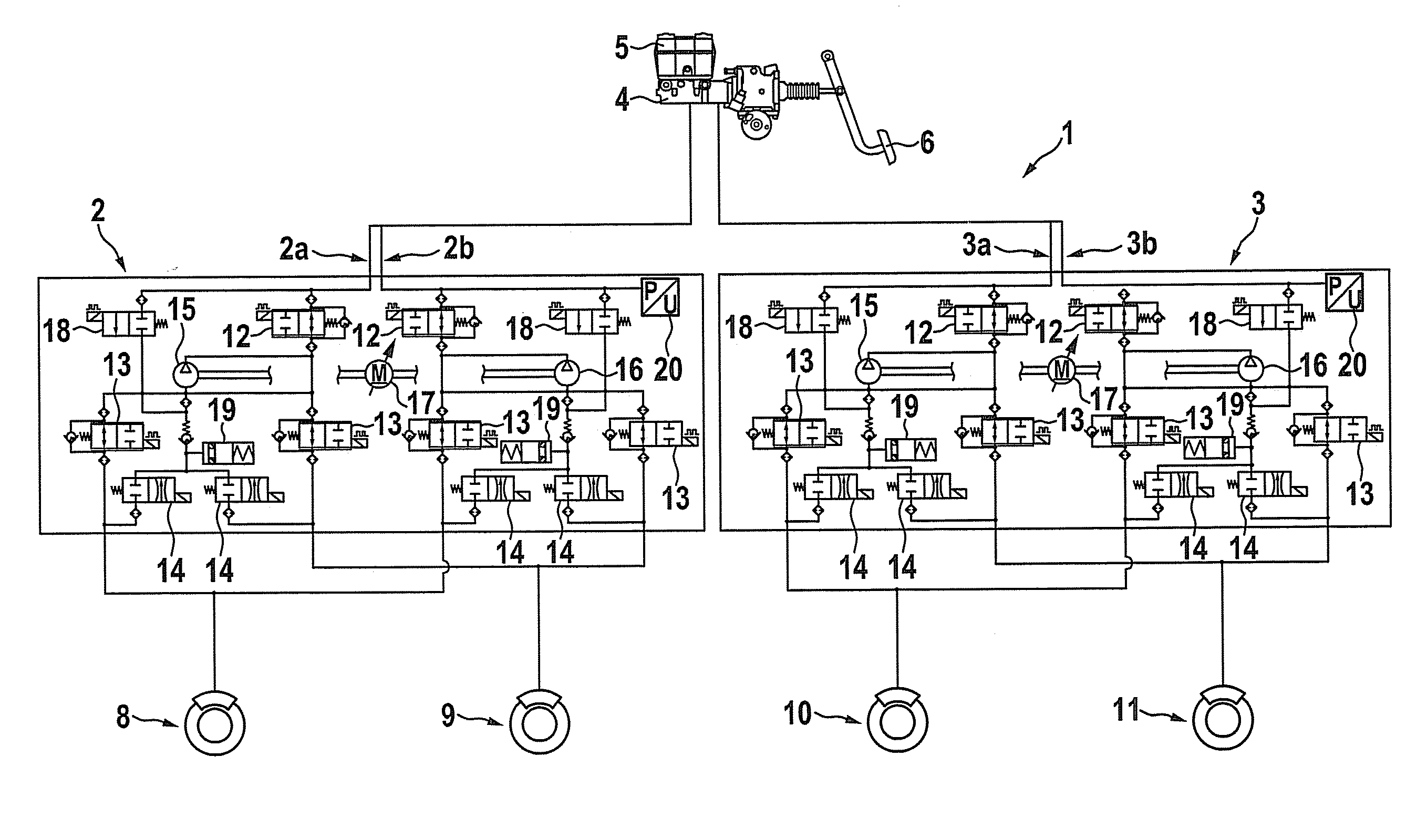
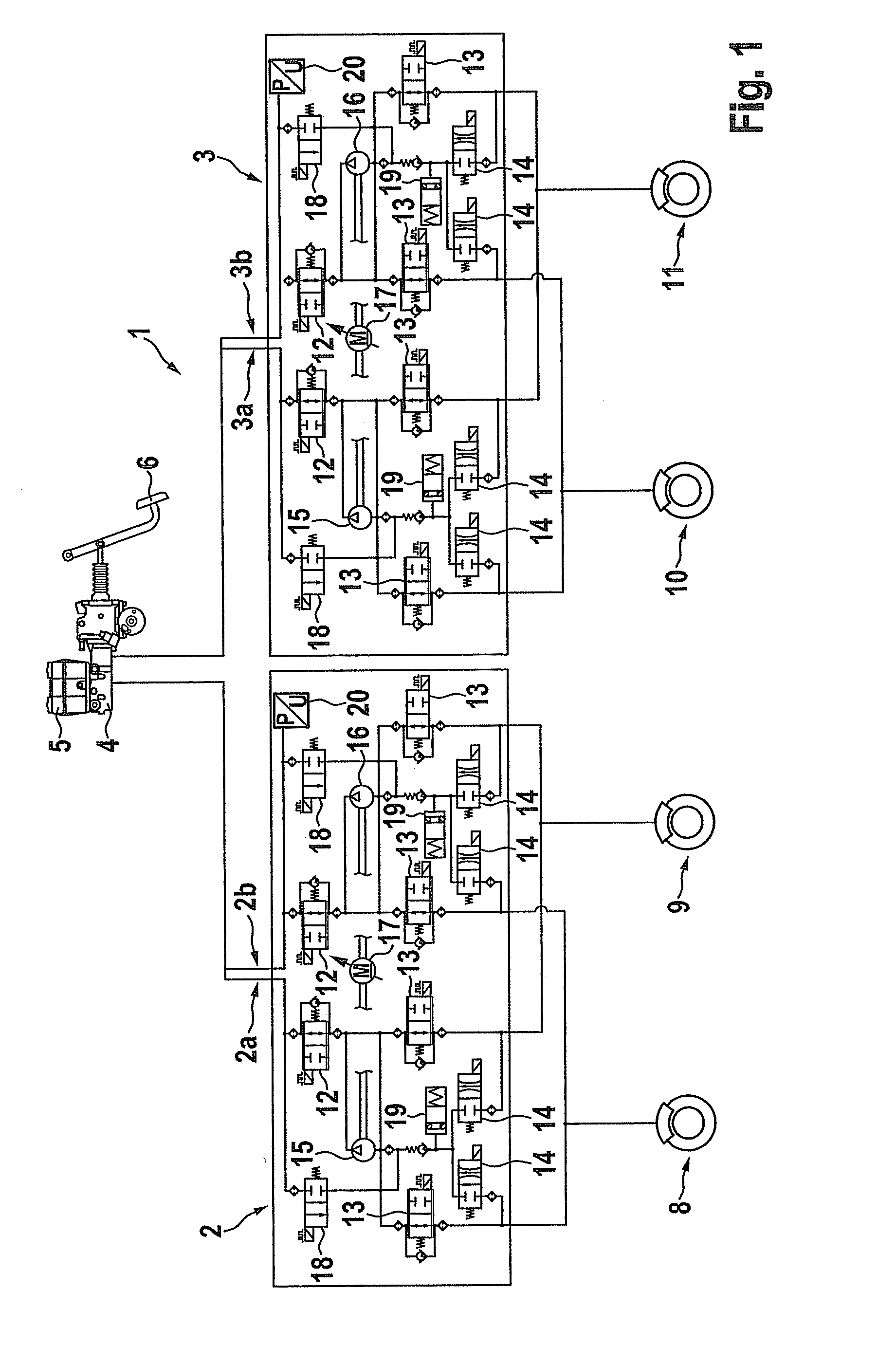
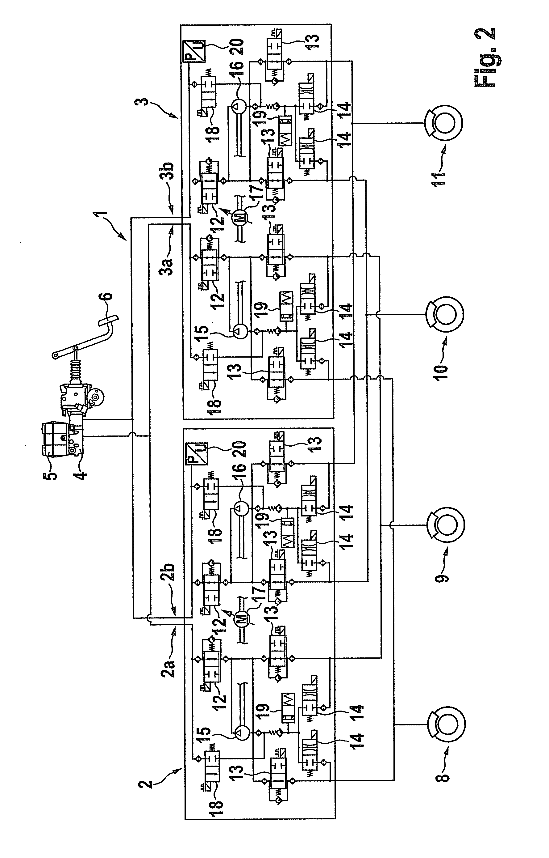
[0014]The hydraulic brake system in a brake installation 1 illustrated in FIG. 1 includes a first brake circuit device 2 and a second brake circuit device 3, each of which is provided with two brake circuits 2a, 2b and 3a, 3b for supplying wheel brake units 8 (left rear wheel), 9 (right rear wheel), 10 (left front wheel) and 11 (right front wheel). The two brake circuit devices 2 and 3, including their brake circuits 2a, 2b and 3a, 3b, are connected to a shared main brake cylinder 4, which is supplied with brake fluid via a brake fluid reservoir 5. Main brake cylinder 4 is operated by the driver via the brake pedal 6. If necessary, the pedal travel of the brake pedal is measured via an assigned pedal travel sensor.

[0015]Brake circuit device 2 is assigned to wheel brake units 8 and 9 on the vehicle's rear axle, while brake circuit device 3 is assigned to wheel brake units 10 and 11 on the vehicle's front axle. Brake circuit devices 2 and 3 have an identical design, so that only the f...


PUM


Abstract

A vehicle brake system has a plurality of hydraulic brake circuits via which wheel brake units are supplied with brake pressure. At least one wheel brake unit is connected to at least two brake circuits and supplied with brake pressure via these two brake circuits.

Description

FIELD OF THE INVENTION[0001]The present invention relates to a vehicle brake system having a plurality of hydraulic brake circuits.BACKGROUND INFORMATION[0002]A hydraulic vehicle brake system which is designed as a dual-circuit brake system having two brake circuits connected to a shared main brake cylinder is described in German Patent No. DE 10 2007 020 503. Each brake circuit acts upon two wheel brake units on the vehicle wheels via adjustable valves. The vehicle brake system has a hydraulic pump unit which includes one pump for each brake circuit and a shared electric drive motor which operates both pumps. Driver assistance systems, for example a vehicle dynamics control system or an electronic stability program, may be supported via the hydraulic pump unit.[0003]In commercial vehicles, in particular, vehicle brake systems of this type may require high pressure buildup gradients to successfully intervene in the vehicle dynamics control system. Increased pressure buildup gradient...

Claims


Application Information

Patent Timeline
Patent Type & Authority Applications(United States)
IPC IPC(8): B60T11/24F16D65/32F16D65/28
CPCB60T8/348B60T8/4872B60T8/5012B60T11/24B60T13/147B60T13/662B60T13/686B60T8/5081
Inventor BRUEGGEMANN, RAINERFRUEH, PHILIPP
Owner ROBERT BOSCH GMBH
Why Eureka
Try Eureka