Battery module state detection method

a battery module and state detection technology, applied in the field of battery module state detection method, can solve the problems of reducing the internal resistance of the battery, the inability to recover whether the process is carried out, and the inability to reduce the ion concentration of the electrolyte and the area, so as to improve the convenience and safety of the battery, simplify the design of the battery module, and prevent the effect of the battery li

Active Publication Date: 2011-09-29
NAT CHUNG SHAN INST SCI & TECH
View PDF4 Cites 37 Cited by
  • Summary
  • Abstract
  • Description
  • Claims
  • Application Information

AI Technical Summary

Benefits of technology

[0012]In conclusion, the operating state of a battery unit, such as the current remaining energy value and lifetime, can be determined according to the variation of the internal resistance measured by the method based on the present invention. Because no external high frequency alternating current is needed to apply on the battery with the method, there is no need of complex equipment. Therefore, the method not only simplifies the design of the battery module and the wi

Problems solved by technology

When the battery is in the recharging process, the abovementioned internal factors will undergo changes in a reverse direction and result in a decreasing internal resistance of the battery.
In practical application, however, with each time the battery is discharged or recharged, the ion concentration of the electrolyte and the area, density and material of the electrode plate will gradually degenerate and can't be recovered whether the process is in the forward or reverse direction.
This situation reflects the fact that those inner factors can never be restored to their best state ever since the battery has been manufactured even if the battery is been recharged.
On the other hand, the internal resistance of the battery will increase rapidly near the end of the discharging cycle, which will induce a rapid rise of internal temperature.
If a battery unit of the battery module comes to its end of the discha

Method used


Image

  • Battery module state detection method
  • Battery module state detection method
  • Battery module state detection method

Examples


Embodiment Construction

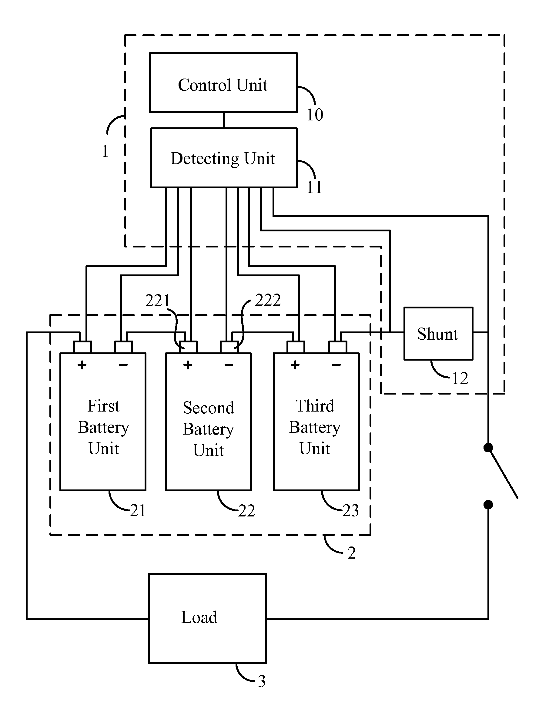
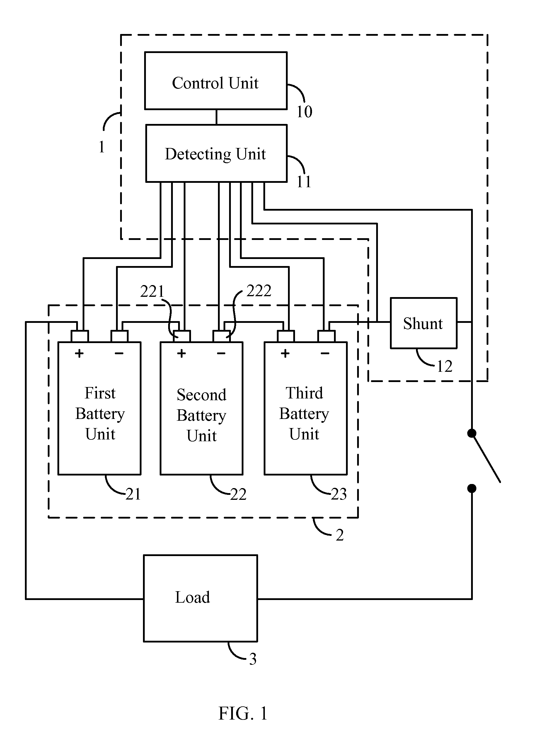
[0017]The present invention provides a battery module state detection method for monitoring the internal resistance of each battery unit in the battery module so that the current remaining energy value and lifetime of the battery unit can be determined. Furthermore, the position that might cause fire hazard in the battery module can be predicted as well. The embodiments of the present invention will be described in the following detailed description.

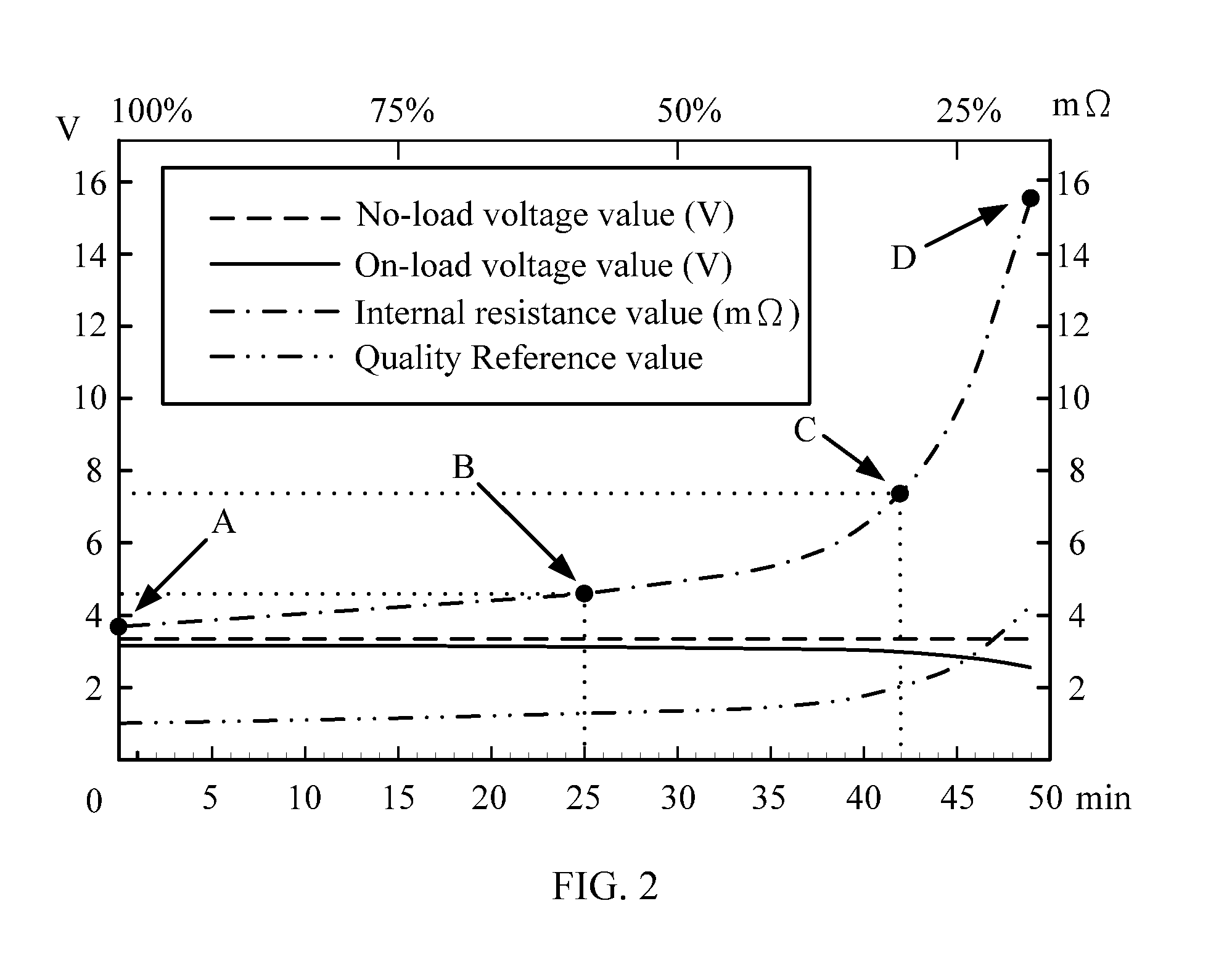
[0018]FIG. 1 is a schematic view of the battery module state detection device 1 according to one embodiment of the present invention. FIG. 2 is a diagram showing the relationship between the voltage and internal resistance verses the discharging time of a battery unit according to one embodiment of the present invention. FIG. 3 is a flow chart of the battery module state detection method according to one embodiment of the present invention. FIG. 4 is a flow chart of the activation of the protection mechanism according to one embodiment o...


PUM


Abstract

The present invention provides a battery module state detection method. The battery module includes a battery unit and is connected to a load. The method for detecting the battery module status includes the following steps. First, measure an on-load voltage value of the battery unit and a load current value of a load. Next, calculate an instant resistance value of the battery unit according to a no-load voltage value of the battery unit, the on-load voltage value and the load current value. Finally, obtain an operating state of the battery unit according to the instant resistance and a relationship between the internal resistance and discharging time. By the method of the present invention, the user can monitor the remaining energy of the battery module accurately in real time and therefore prevent the electrical hazard caused by over-discharging the battery module.

Description

BACKGROUND OF THE INVENTION[0001]1. Field of the Invention[0002]The present invention generally relates to battery module state detection method, and more particularly, to a detection method of measuring the internal resistance of the battery unit of the battery module during the regular discharging operation thereof as an index of the lifetime and quality of the battery module.[0003]2. Description of the Prior Art[0004]Generally, a real battery should have its own internal resistance comparing to an ideal battery. The internal resistance of the battery is determined by the internal factors such as the ion concentration in the electrolyte, as well as the area, density and material of the electrode plate. During the discharging process of the battery, the abovementioned internal factors will undergo changes in a forward direction and therefore result in the increasing internal resistance of the battery. When the battery is in the recharging process, the abovementioned internal factor...

Claims


Application Information

Patent Timeline
IPC IPC(8): H02J7/00G01N27/416
CPCG01R31/3662G01R31/3658G01R31/389G01R31/396
Inventor LIU, CHIN-CHUAN
Owner NAT CHUNG SHAN INST SCI & TECH
Why Eureka
Try Eureka