Wound iron core for static apparatus, amorphous transformer and coil winding frame for transformer
- Summary
- Abstract
- Description
- Claims
- Application Information
AI Technical Summary
Benefits of technology
Problems solved by technology
Method used
Image

Examples
embodiment 1
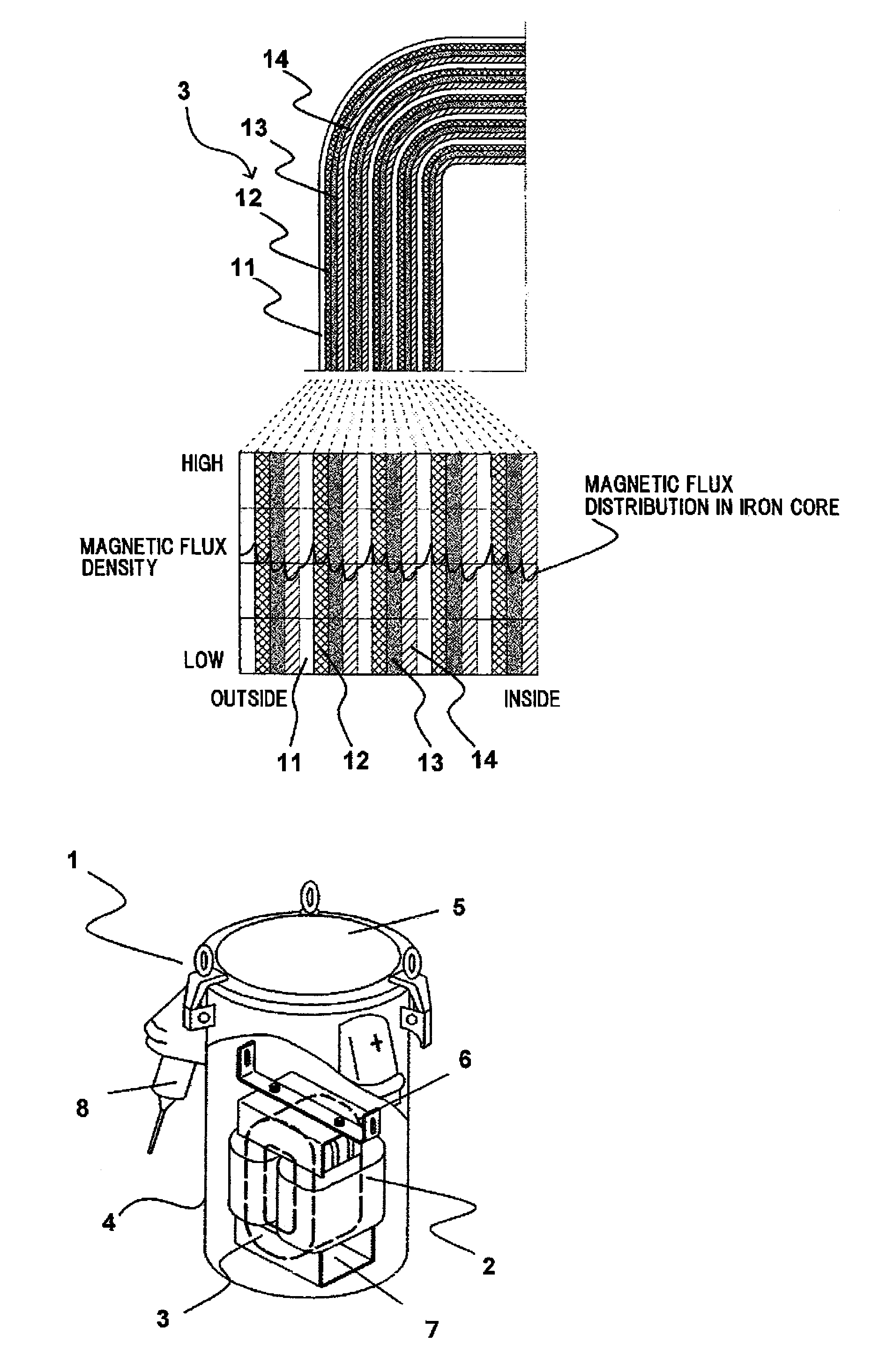
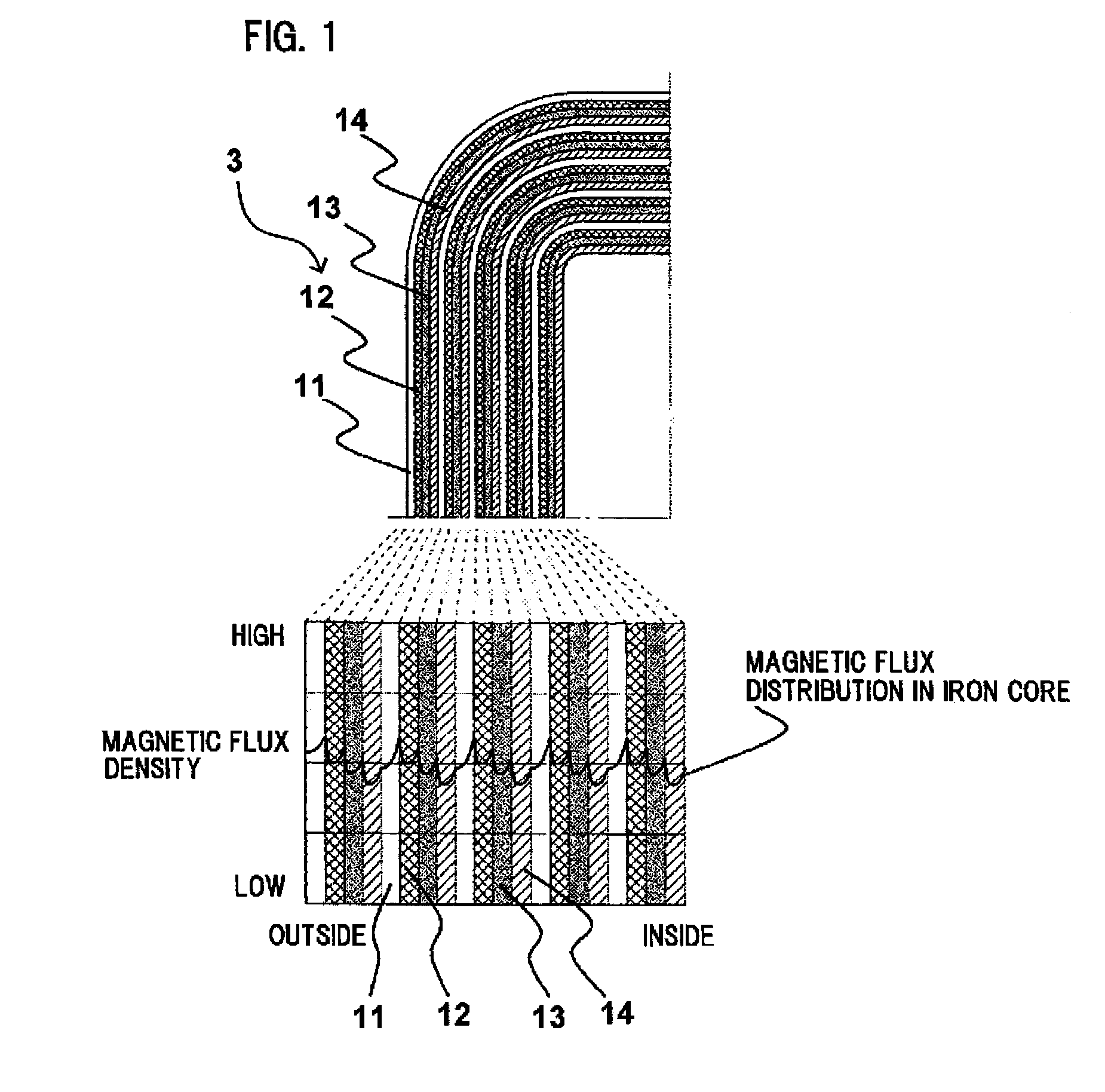
[0169]FIG. 1 shows a partial cross-sectional view of a wound iron core 3 using four kinds of magnetic steel sheets with different magnetic permeabilities. When the respective magnetic permeabilities of the four kinds of magnetic steel sheets constituting the wound iron core 3 are referred to as μ1, μ2, μ3 and μ4 and the respective magnetic steel sheets satisfy a relationship of μ1234, the magnetic steel sheet having a small magnetic permeability (magnetic permeability μ1) is arranged on the inner side of the iron core, the magnetic steel sheet having a magnetic permeability μ2 is disposed on the next layer on the outer side thereof, the magnetic steel sheet having a magnetic permeability μ3 is disposed on the next layer on the outer side thereof, and the magnetic sheet having a magnetic permeability μ4 is disposed as the next layer on the outer side thereof, wherein these layers formed of four kinds of magnetic steel sheets constitute a single block, and these blocks are repeatedly ...
embodiment 2
[0177]FIG. 5 shows an arrangement in which an iron core is formed by laminating two kinds of materials with different magnetic permeabilities.
[0178]In this example, an amorphous material SA1 (Hitachi Metals, product name 2605SA1) and an amorphous material HB1 (Hitachi Metals, product name 2605HB1) having a higher magnetic flux density than SA1 were used as the two materials with different magnetic permeabilities.
[0179]In FIG. 5, the iron core 15 is formed by disposing an amorphous material in which the magnetic permeability is reduced when the core is annealed at a certain temperature on the inner circumference side of the core, laminating an amorphous material in which the magnetic permeability is increased when annealed as the next layer, and repeating such arrangement to constitute the amorphous iron core.
[0180]The amorphous material 15 having a small magnetic permeability can be formed of a single plate or a plurality of plates, and the amorphous material having a greater magnet...
embodiment 3
[0186]FIG. 7 shows a partial cross-sectional view of an iron core formed by laminating two kinds of amorphous ribbons with different magnetic permeabilities.
[0187]In FIG. 7, the inner iron core is formed by laminating a single plate or a plurality of plates of amorphous ribbons (material 14) with a small magnetic permeability, laminating as the next layer an amorphous ribbon (material 11) with greater magnetic permeability, and alternately repeating such lamination, wherein the laminated amount, or thickness, of amorphous ribbons having greater magnetic permeability is gradually increased. The thickness of the amorphous ribbon 14 is substantially the same, that is, the values of A1, A2, A3, A4 and A5 are substantially equal.
[0188]The laminated thickness of the amorphous ribbons having greater magnetic permeability is L12345, wherein the amount of thickness is increased proportionally. However, it is possible to set the thickness at the center portion of the iron core to be substanti...
PUM
 Abstract
Description
Claims
Application Information
 - R&D
- Intellectual Property
- Life Sciences
- Materials
- Tech Scout
- Unparalleled Data Quality
- Higher Quality Content
- 60% Fewer Hallucinations
Browse by: Latest US Patents, China's latest patents, Technical Efficacy Thesaurus, Application Domain, Technology Topic, Popular Technical Reports.
© 2025 PatSnap. All rights reserved.Legal|Privacy policy|Modern Slavery Act Transparency Statement|Sitemap|About US| Contact US: help@patsnap.com