Cable connector

Active Publication Date: 2015-12-22
WELL SHIN TECH
View PDF22 Cites 4 Cited by
  • Summary
  • Abstract
  • Description
  • Claims
  • Application Information

AI Technical Summary

Benefits of technology

[0010]As described above, the cable connector is fastened to the mating connector by virtue of increasing the insertion and withdrawal forces between the cable connector and the mating connector so as to ensure it's difficult for the cable connector to loosen or fall off from the mating connector in the process of the electronic device working. When persons or cargoes are accidentally stumbled by the cable, it's able to disconnect th

Problems solved by technology

In the process of operating the electronic device, if the cable connector is caused to loosen or fall off on account of being accidentally touched by a person, that will make the electronic device stop working to bring an inconvenience for a user, so it can be seen that a lot of mating connectors and cable connectors having locking mechanisms sold on market.
However, if some electronic devices together with the cables are disposed to moving lines of the persons walking arou

Method used


Image

  • Cable connector
  • Cable connector
  • Cable connector

Examples


Example

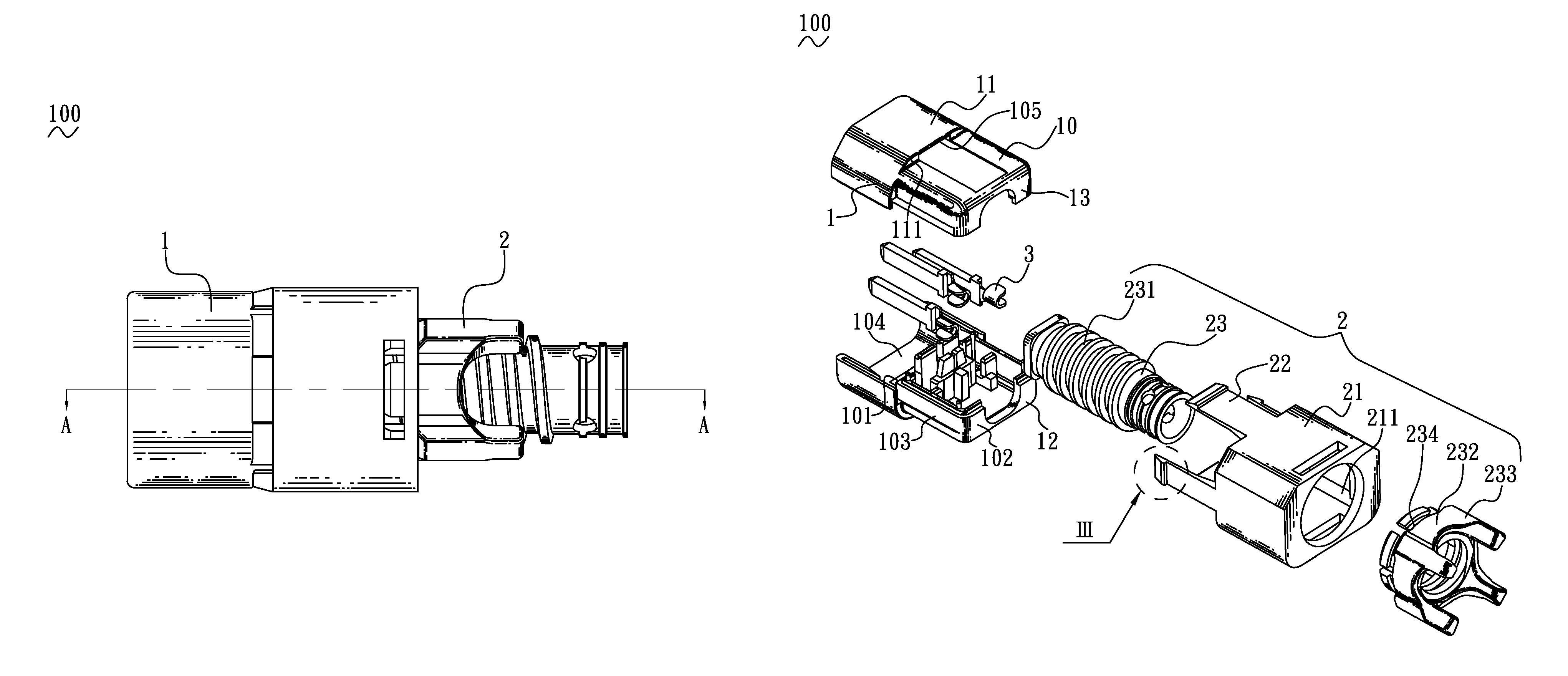
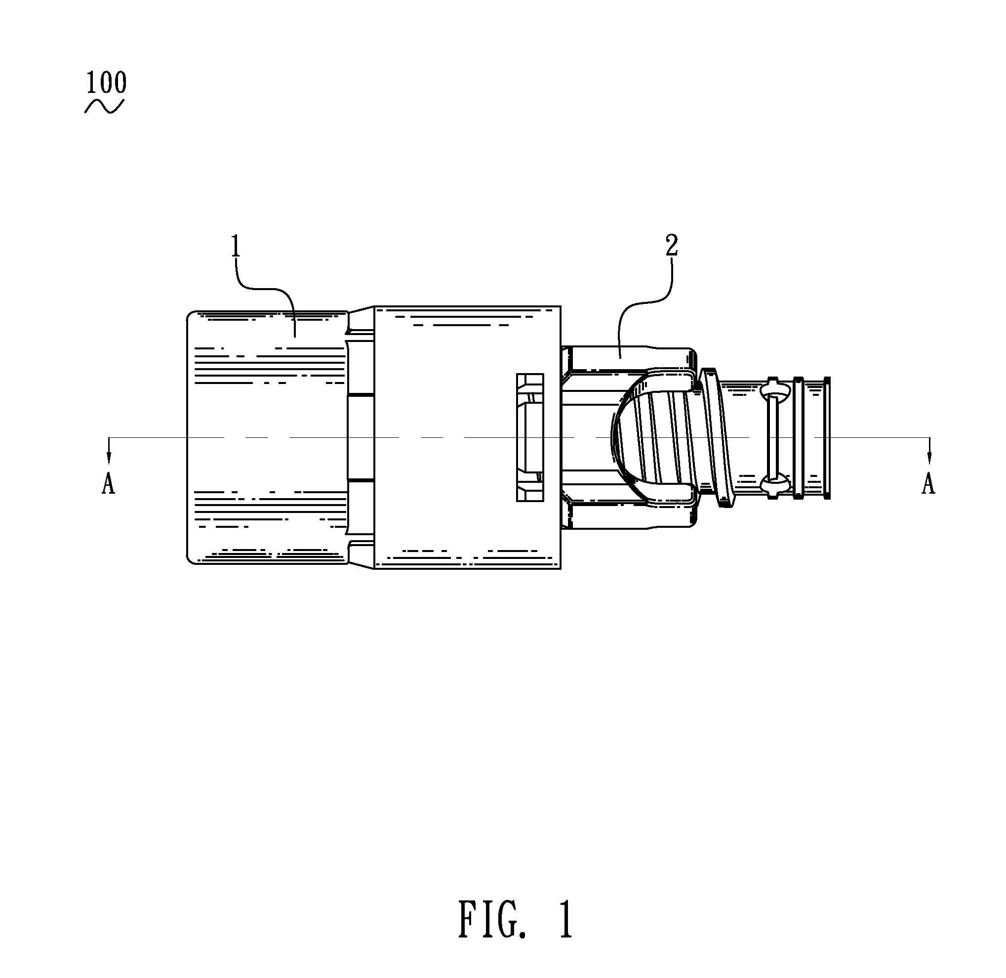
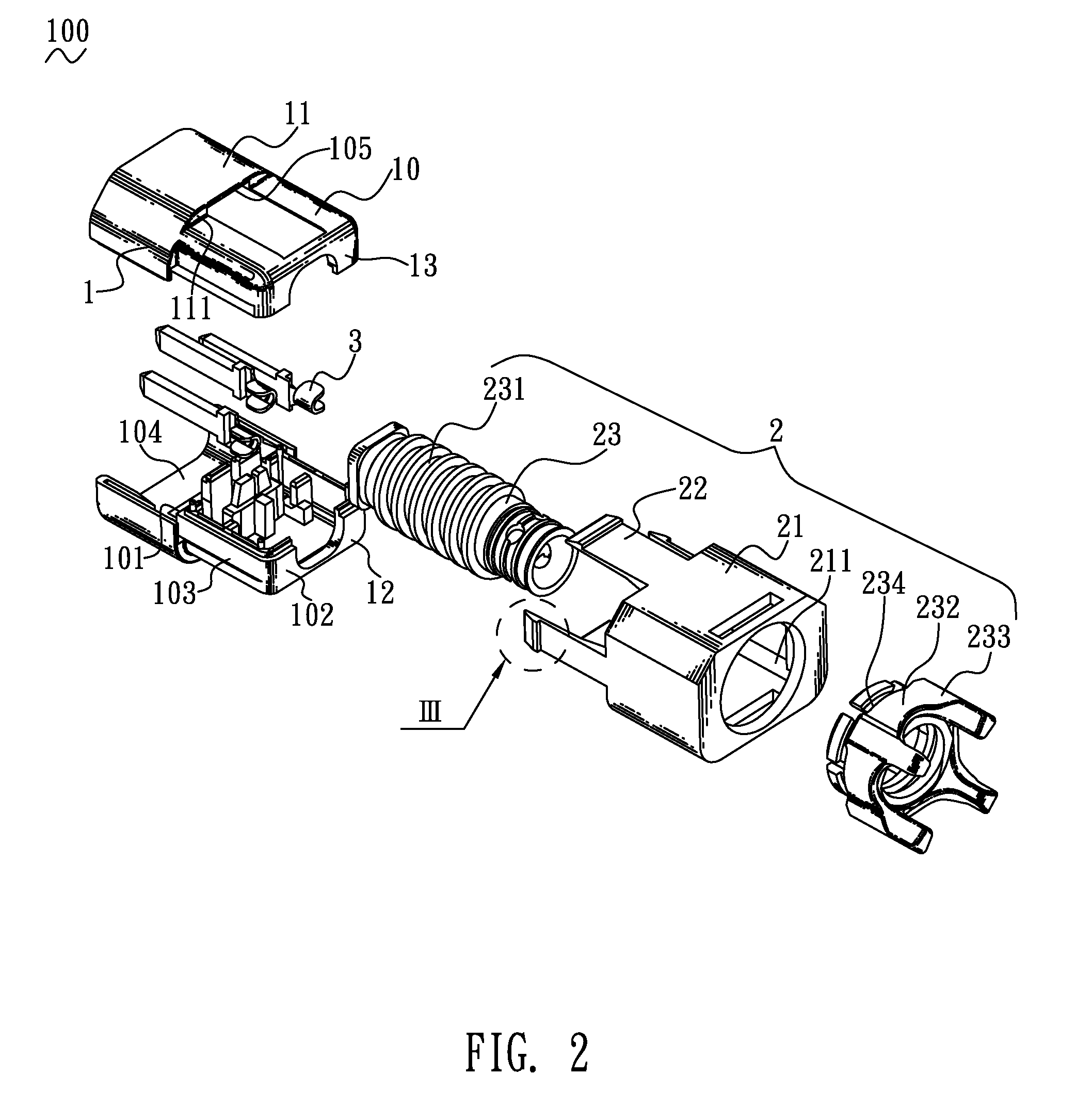
[0016]Referring to FIG. 1 and FIG. 2, a cable connector 100 in accordance with an embodiment of the present invention is shown. The cable connector 100 adapted for being electrically connected with a mating connector (not shown), includes an insulating housing 1, a locking mechanism 2 and at least one conductive terminal 3. The locking mechanism 2 is connected with the insulating housing 1 for increasing insertion and withdrawal forces between the cable connector 100 and the mating connector.

[0017]Referring to FIG. 1 and FIG. 2, the insulating housing 1 includes a hollow rear housing 10 and a substantially barrel-shaped front housing 11. A front end and a rear end of the rear housing 10 are opened freely. A front end and a rear end of the front housing 11 are opened freely. The rear housing 10 has a front surface 101, a rear surface 102 opposite to the front surface 101, and an outer surface 103 connected between the front surface 101 and the rear surface 102. In this embodiment, th...


PUM


Abstract

A cable connector includes an insulating housing, at least one conductive terminal disposed in the insulating housing, and a locking mechanism. The insulating housing includes a rear housing and a substantially barrel-shaped front housing. A periphery of a rear end of the front housing and the periphery of a front surface of the rear housing are connected with a connecting wall. The connecting wall defines at least one insertion groove. The locking mechanism includes a sleeve element and a feed assembly. The sleeve element is capable of moving forward and rearward along the rear housing. The feed assembly is disposed to a rear end of the rear housing. The feed assembly is connected to the sleeve element for controlling the sleeve element to move forward and rearward along the rear housing.

Description

CROSS-REFERENCE TO RELATED APPLICATION[0001]The present application is based on, and claims priority form, Taiwan Patent Application No. 103214374, filed Aug. 12, 2014, the disclosure of which is hereby incorporated by reference herein in its entirety.BACKGROUND OF THE INVENTION[0002]1. Field of the Invention[0003]The present invention generally relates to a cable connector, and more particularly to a cable connector having a locking mechanism.[0004]2. The Related Art[0005]In general, an electronic device and a power supply are connected by a cable to realize an electrical connection therebetween. One end of the cable is connected with a cable connector. The cable connector is adapted for being electrically connected with a mating connector which is assembled to the electronic device so as to provide power supply input for the electronic device. For example, an IEC C14 connector is connected with an IEC C13 connector for providing the power supply input.[0006]Usually, many electroni...

Claims


Application Information

Patent Timeline
IPC IPC(8): H01R13/58H01R13/621H01R24/28
CPCH01R24/28H01R13/621H01R13/506H01R13/5812H01R13/59H01R13/62H01R13/639H01R13/585H01R13/6392H01R13/6395H01R13/6397H01R13/64H01R13/641H01R13/642H01R13/645H01R13/6453H01R13/6456
Inventor LIAO, HUI REN
Owner WELL SHIN TECH
Why Eureka
Try Eureka