Method and device for suctioning the boundary layer

Active Publication Date: 2009-01-22
AIRBUS OPERATIONS GMBH
View PDF2 Cites 16 Cited by
  • Summary
  • Abstract
  • Description
  • Claims
  • Application Information

AI Technical Summary

Benefits of technology

[0007]In principle, the present invention makes use of the presence of an air-conditioning system in larger aircraft. Therefore, the present invention brings together two system modules of a modern aircraft which until now functioned completely independently of one another. The synergistic effect resulting therefrom is expressed in a reduction of aerodynamic flow losses on the aircraft. This is because by introducing the air of the boundary layer suctioning system into the cabin system, i.e., its air-conditioning system, less bleed air must be taken from the power plant than in the related art, which leads

Problems solved by technology

Releasing the suctioned air to the outside through an outlet placed in the region of the cabin window has also already been attempted; however, this solution, which is simple, has not been shown to be favorable to flow.
A disadvantage in principle of all above-mentioned solutions may be

Method used


Image

  • Method and device for suctioning the boundary layer
  • Method and device for suctioning the boundary layer

Examples


Example

[0012]Further measures and features of exemplary embodiments of the present invention will be explained in greater detail in the following on the basis of the figures, together with the description of a preferred exemplary embodiment of the present invention.

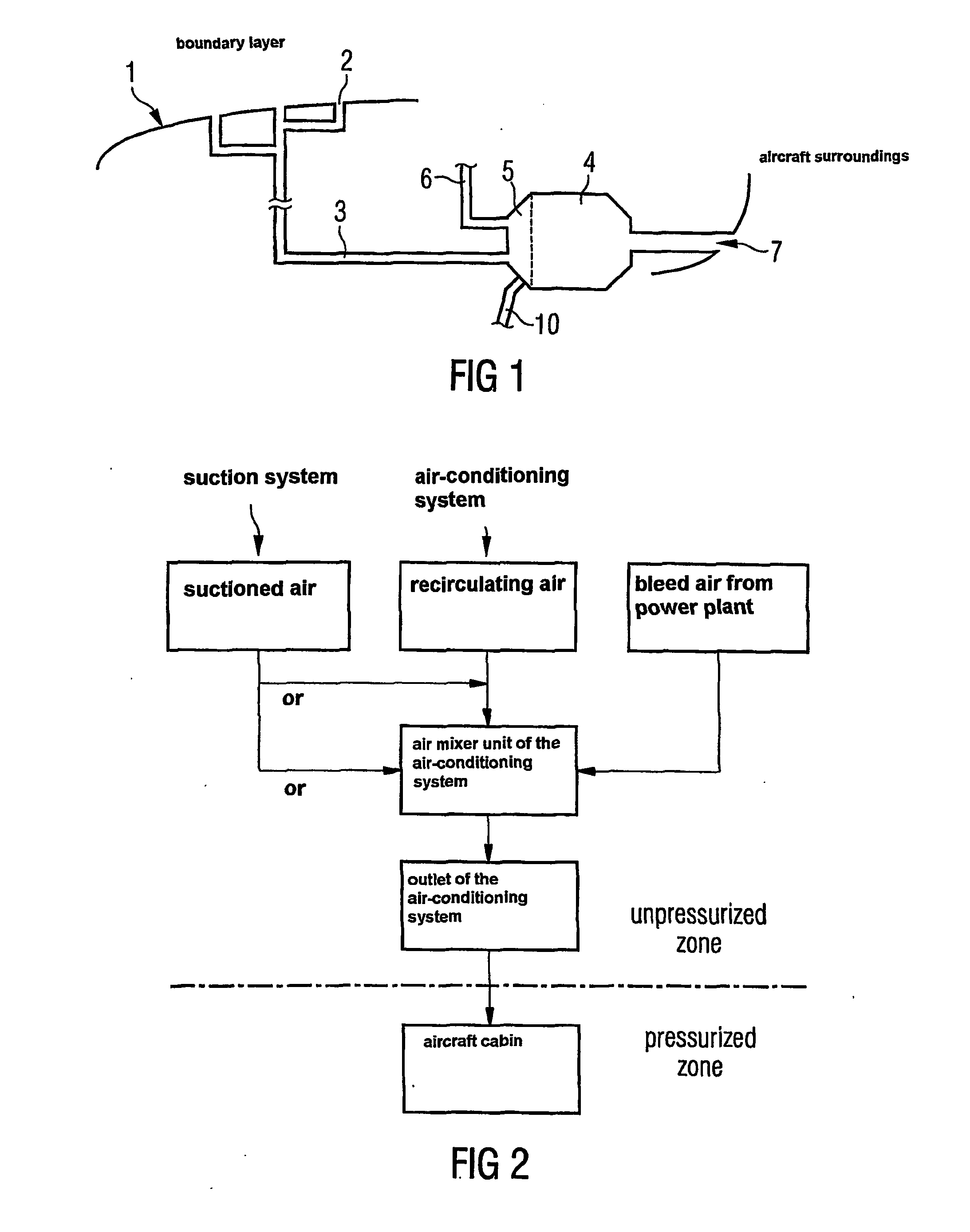
[0013]FIG. 1 shows a schematic illustration of a device for suctioning the boundary layer at the surface of an aircraft, and

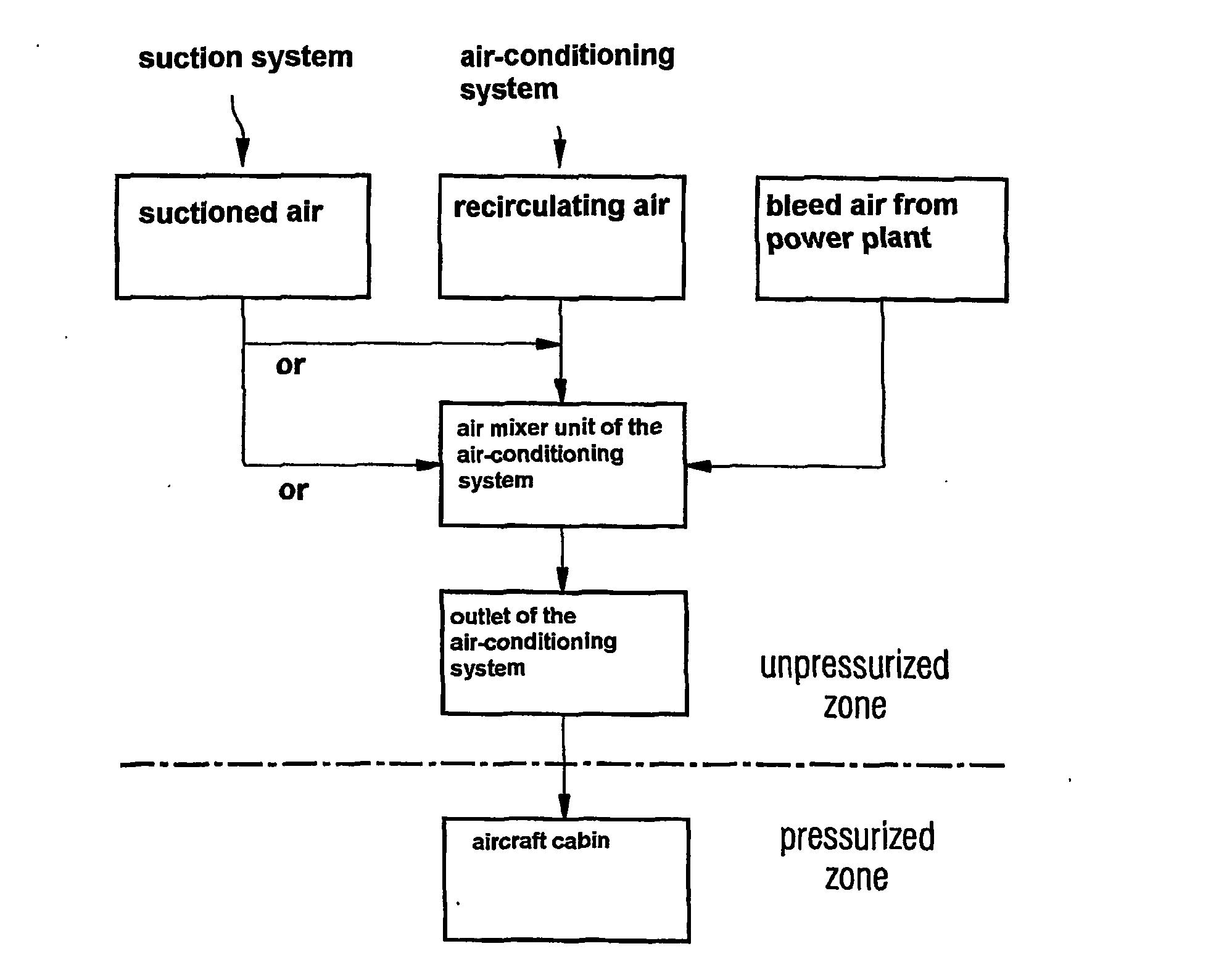
[0014]FIG. 2 shows a schematic flowchart illustration of the suctioning method executable using the device from FIG. 1.

[0015]According to FIG. 1, the surface 1 of an aircraft is provided with many small suction openings 2. The suction openings 2 are positioned at flow-critical points of the surface 1 (shown purely schematically here). During flight, the air flow runs along the surface 1, the air layer proximal to the surface being referred to as the boundary layer. In order to keep this layer laminar even at a high flow speed, the boundary layer is suctioned through the suction openings 2. The suction openi...


PUM


Abstract

A method for suctioning the boundary layer at the surface (1) of an aircraft having an air-conditioning system (4), at whose flow-critical points of the surface multiple suction openings (2) are provided, the air quantity suctioned via these being discharged to the atmosphere again via at least one outlet (7) placed in a way favorable for flow, the air quantity suctioned from the surface (1) being fed to the air-conditioning system (4) of the aircraft, via whose outlet (7) the air quantity suctioned is discharged to the atmosphere together with the exhaust air of the air-conditioning system (4), to reduce flow losses.

Description

FIELD OF THE INVENTION[0001]The present invention relates to a method and a device for suctioning the boundary layer at the surface of an aircraft having an air-conditioning system, at whose flow-critical points of the surface, boundary layer suctioning is applied through small openings.[0002]In the technical field of airplane construction and in aircraft construction in general, suctioning of the air layer flowing directly along the aerodynamic surface regions of the aircraft, the boundary layer, may be performed to reduce the aerodynamic frictional resistance during flight. This measure is based on the fluidic law that the aerodynamic frictional resistance of laminar boundary layer flows is significantly smaller than that of turbulent boundary layer flows. Therefore, the frictional resistance of an aircraft may be reduced while cruising by keeping the boundary layer flow at wing and tail assembly surfaces at least partially laminar. One method for delaying the change from laminar ...

Claims


Application Information

Patent Timeline
IPC IPC(8): B64C21/06B64D13/06B64C21/02B64D13/08
CPCB64C21/025Y02T50/56Y02T50/166B64D2013/0622Y02T50/10Y02T50/50
Inventor SCHRAUF, GEZA
Owner AIRBUS OPERATIONS GMBH
Why Eureka
Try Eureka