Projector

Inactive Publication Date: 2011-09-29
SEIKO EPSON CORP
View PDF3 Cites 8 Cited by
  • Summary
  • Abstract
  • Description
  • Claims
  • Application Information

AI Technical Summary

Benefits of technology

[0009]An advantage of some aspects of the invention is that it provides a projector which can suppress fluctuation of the focal position of the projection optical device.
[0011]Accordingly, the heating unit under the control of the control unit heats the projection optical device so that the temperature of the projection optical device is equal to or higher than the temperature in which the focal position of the projection optical device is stabilized. Thus, as the focal position is adjusted after the temperature of the projection optical device reaches the temperature in which the focal position is stabilized or higher, it is possible to suppress the change in the focal position of the projection optical device before and after adjustment. Accordingly, the image can be displayed clearly.
[0013]In this respect, for example, if a heater is employed as the heating unit, noise such as wind noise can be suppressed, and silencing of the projector can be obtained compared with a case where the cooling unit is used.

Problems solved by technology

However, in the projector disclosed in JP-A-3-149538, since the focal position of the projection optical device is adjusted on the basis of the distance between the projector and the screen, it is difficult to correct “out of focus” in the focal position of the projection optical device occurring due to the temperature.
Thus, the focal position of the projection optical device set on the basis of the above-described distance is changed between the low temperature and the high temperature, and thus, the projection image cannot be displayed clearly.
However, in a case where such a fan is installed, since wind noise due to the blowing of the cooling air occurs, silence of the projector is interrupted.

Method used


Image

  • Projector
  • Projector
  • Projector

Examples


Embodiment Construction

[0022]Hereinafter, embodiments of the invention will be described with reference to the accompanying drawings.

Configuration of Projector

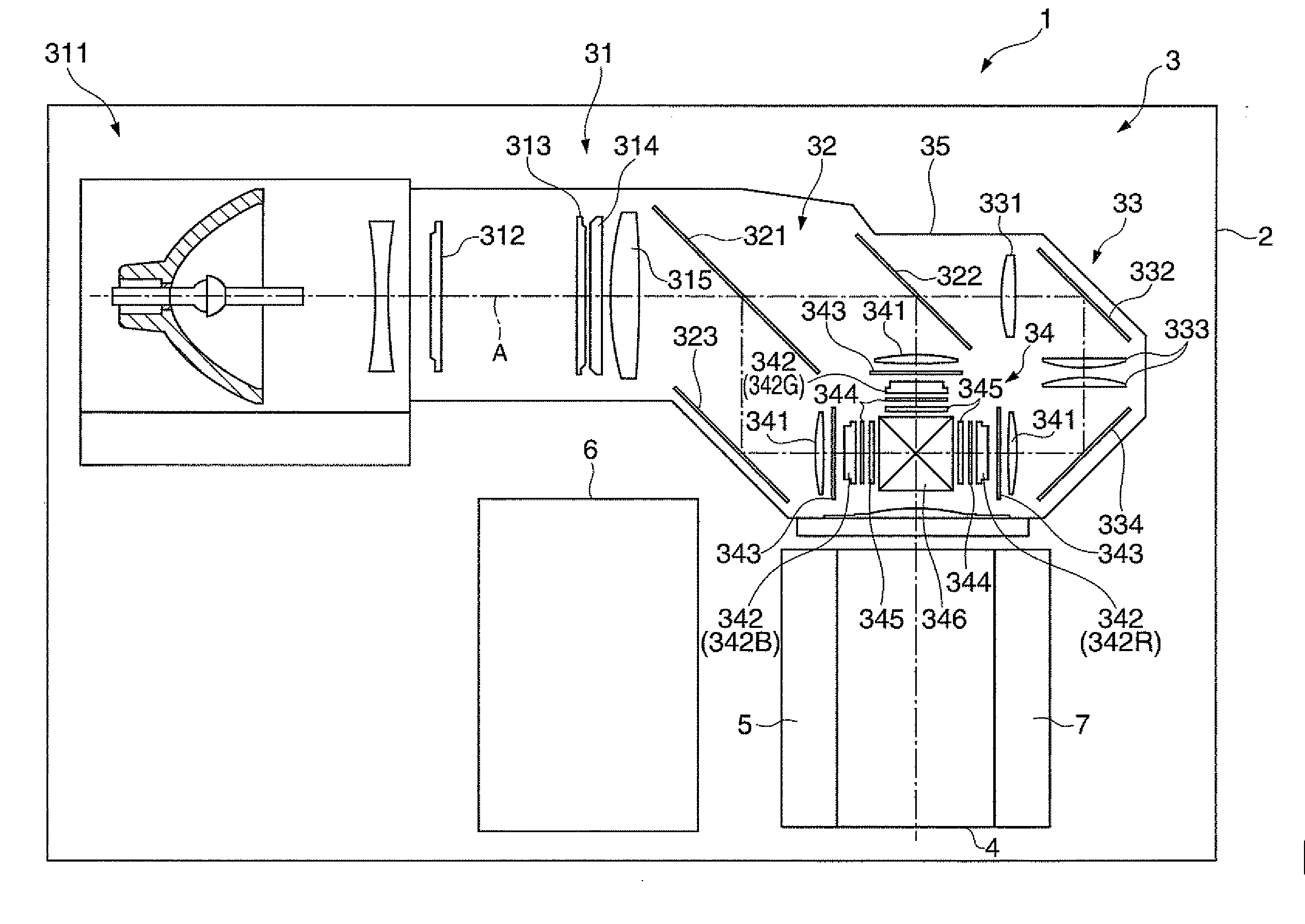
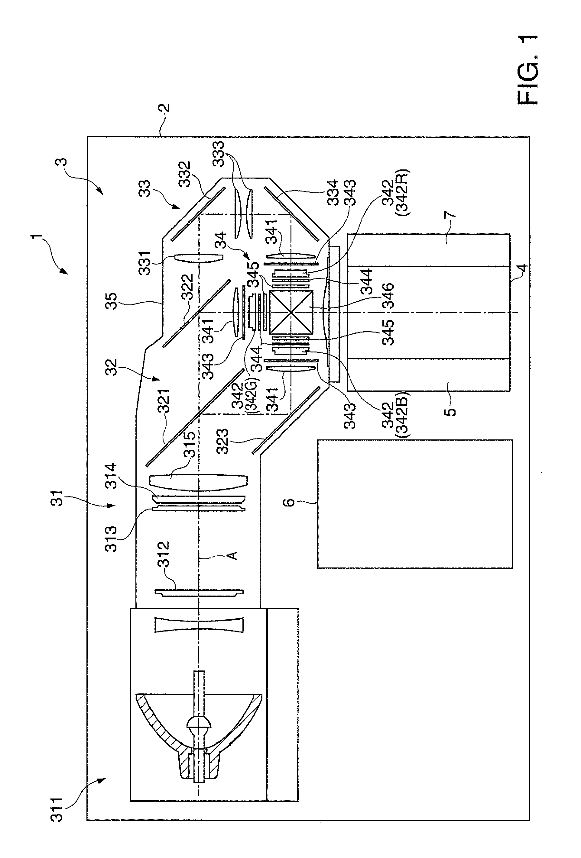
[0023]FIG. 1 is a schematic diagram illustrating a configuration of a projector 1 according to an embodiment of the invention.

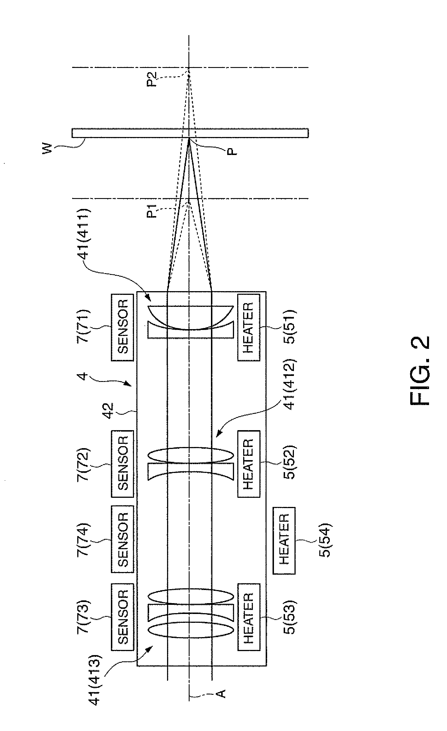
[0024]The projector 1 according to this embodiment modulates a light flux emitted from a light source device 311 which is installed therein, forms an image according to image information, and enlarges and projects the image onto a projection target surface W (see FIG. 2) such as a screen. As shown in FIG. 1, the projector 1 includes an external housing 2, an image forming device 3, a projection optical device 4, a heating unit 5, a control unit 6, and a temperature sensor 7.

[0025]Among them, the external housing 2 is formed in an approximately rectangular parallelepiped shape of synthetic resin or metal, and accommodates and arranges the above described respective devices 3 and 4, the respective units 5 and 6, and the like th...


PUM


Abstract

A projector which includes a projection optical device which projects an image includes: a heating unit which heats the projection optical device; and a control unit which controls the heating unit, wherein the control unit controls the heating unit so that the temperature of the projection optical device is equal to or higher than the temperature in which a focal position of the projection optical device is stabilized.

Description

BACKGROUND[0001]1. Technical Field[0002]The present invention relates to a projector.[0003]2. Related Art[0004]In the related art, there has been known a projector which includes a light source device, a light modulating device which modulates light flux emitted from the light source device to form an image light corresponding to image information, and a projection optical device which enlarges and projects the image light onto a projection target surface such as a screen. Many of these projection optical devices employ a coupling lens in which a plurality of lenses such as a zoom lens and a focusing lens is installed in a lens barrel.[0005]However, in a case where the image is to be displayed clearly on the projection target surface corresponding to the image light emitted from the projection optical device during use of the projector, it is necessary to adjust a focal position of the projection optical device. In this regard, there is known a projector which automatically adjusts ...

Claims


Application Information

Patent Timeline
IPC IPC(8): G03B21/16
CPCG03B21/16H04N9/317H04N9/3144
Inventor KUDO, YUSUKE
Owner SEIKO EPSON CORP
Why Eureka
Try Eureka