

Structure for connecting connector, and head lamp light source lighting device using the structure
a technology of connecting connectors and structures, which is applied in the direction of fixed connections, coupling device connections, transportation and packaging, etc., can solve the problems of inability to maintain the appropriate contact pressure for a long time, the occurrence of contact failures caused by oxidation on the surface of solder, and the reliability of contact, so as to reduce the occurrence of contact failures, enhance the reliability of connector connection, and simple pressing operation
- Summary
- Abstract
- Description
- Claims
- Application Information
AI Technical Summary
Benefits of technology
Problems solved by technology
Method used
Image

Examples
first embodiment
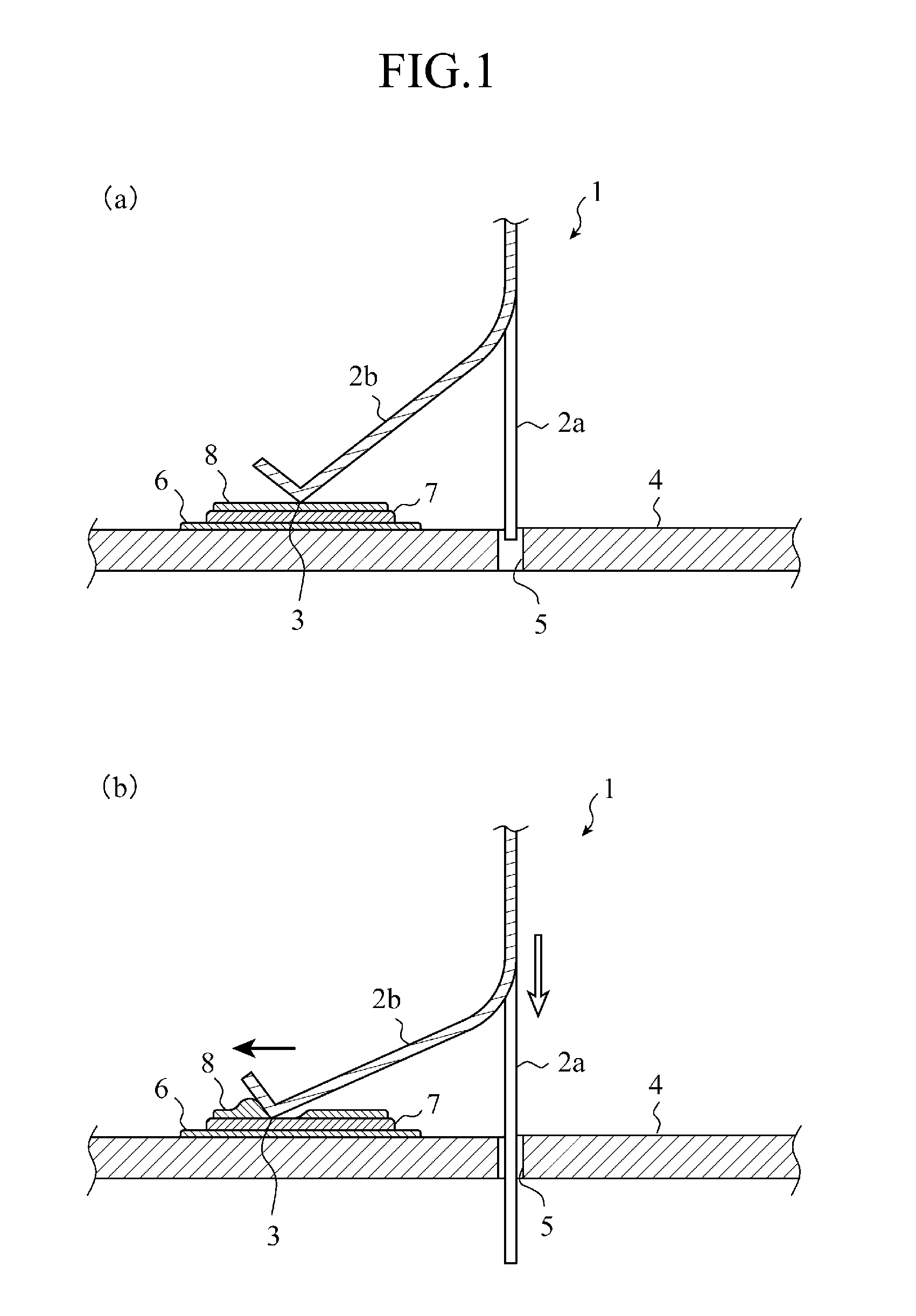
FIG. 1 is a view showing a connector connecting structure in accordance with a first embodiment of the present invention, and shows a cross-section of a board 4 with a connector terminal 1 taken in a longitudinal direction thereof. In a connector connecting structure in accordance with the first embodiment, the connector terminal 1 includes an insertion section 2a and a moving section 2b, and the insertion section 2a is inserted into a hole (through hole) 5 of a board 4 from the state shown in FIG. 1(a) in the direction of the white arrow shown in FIG. 1(b), thus providing an electrical connection between a contact portion 3 of the moving section 2b and a tinned face 7 of an electrode 6 on the board 4.
The moving section 2b of the connector terminal 1 is provided with jutting out obliquely with respect to an inserting direction of the insertion section 2a into the hole 5, and also has resilience to be flexible according to the operation of inserting the insertion section 2a into the ...
second embodiment
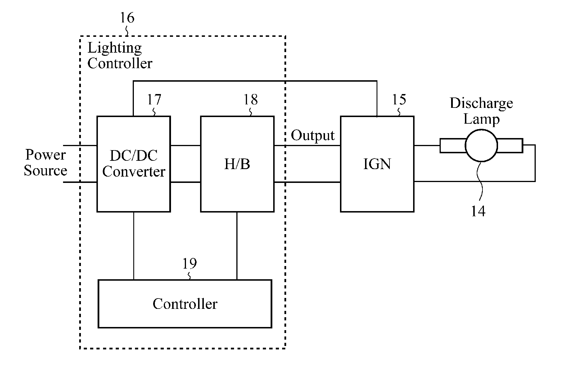
In a second embodiment, an arrangement will be discussed in which a connector connecting structure shown in the first embodiment is applied to at least one of a source power input connecting section and a connecting section for outputting power for a light source in a lighting device for lighting a light source for a vehicle-mounted headlamp.
FIG. 6 is a block diagram showing schematically an arrangement of a lighting device in accordance with the second embodiment of the present invention. Referring to FIG. 6, the lighting device in accordance with the second embodiment includes a discharge lamp 14, an igniter (IGN) 15, and a lighting controller (controlling unit) 16. The igniter 15 triggers the discharge lamp 14 to discharge by using the power source voltage for the igniter inputted thereto from the lighting controller 16. The lighting controller 16 is a unit that inputs power thereto from a power source and outputs the light source power for lighting the discharge lamp 14, and the...
PUM
 Abstract
Description
Claims
Application Information