Efficient deployment of mobility management entity (MME) with stateful geo-redundancy

Inactive Publication Date: 2011-09-29
HITACHI LTD
View PDF6 Cites 115 Cited by
  • Summary
  • Abstract
  • Description
  • Claims
  • Application Information

AI Technical Summary

Benefits of technology

[0010]The foregoing has outlined some of the more pertinent features of the subject matter. These features should be construed to be merely illustrative. Many

Problems solved by technology

Nevertheless, when the user moves to a new MME node, all the existing sessions, calls in progress, and the like, get dropped.
The reason this is the case is that the S1-Flex mechanism does not provide for

Method used


Image

  • Efficient deployment of mobility management entity (MME) with stateful geo-redundancy
  • Efficient deployment of mobility management entity (MME) with stateful geo-redundancy
  • Efficient deployment of mobility management entity (MME) with stateful geo-redundancy

Examples


first embodiment

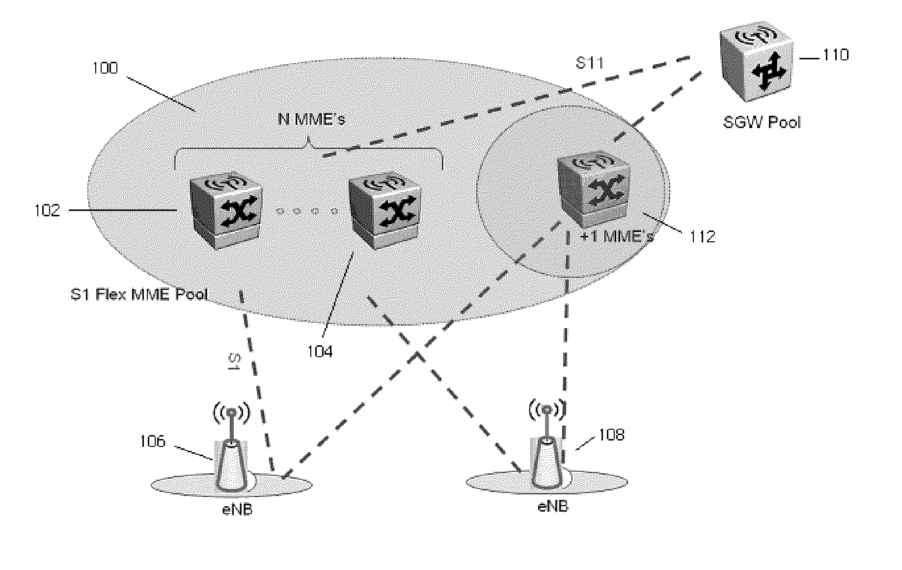
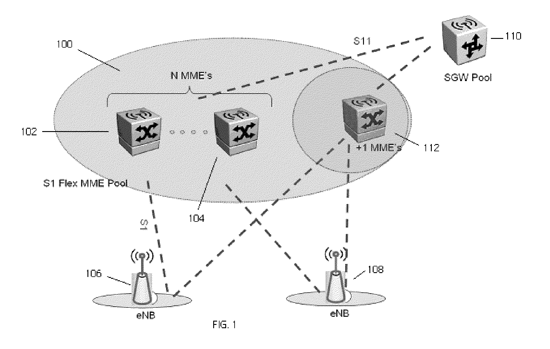
[0019]In a first embodiment, involving BGP, the backup site and the other sites are connected via a BGP router to the access network and on S11 for the backup MME to take over the S1 IP address of the failed MME. In this approach, the latency of routing information propagation between the MME sites and the BGP router should be less than the S1 SCTP association timeout in the eNodeB (to prevent the eNodeB from releasing the SCTP association).

second embodiment

[0020]In a second embodiment, SCTP multi-homing from the eNB to both the active MMEs and the standby MME is utilized to obviate the BGP router on the S1 interface. On the S11 interface, proprietary signaling between the MME and S-GW is utilized to remove the need for BGP router on this interface as well.

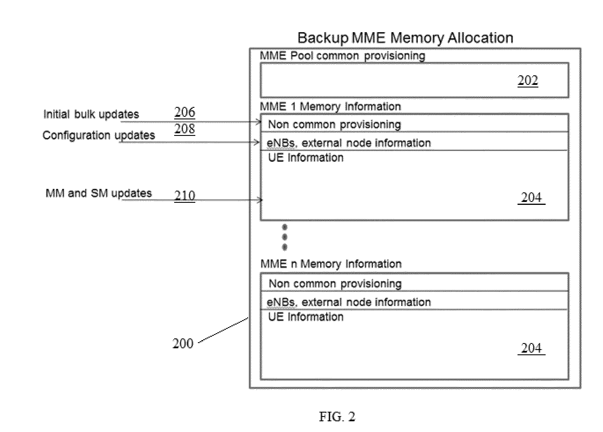
[0021]The following provides additional details regarding the above-described technique. According to 3GPP TS 23.401, Section 5.7.2, an MME maintains Mobility Management (MM) context and EPS bearer context information for UEs in one of several states: ECM-IDLE, ECM CONNECTED, and EMM-DEREGISTERED states. During initialization of an active MME, and according to this disclosure, the MME's configuration information (including, without limitation, IP addresses on all interfaces, supported Tracking Areas (TA), SCTP association information, and the like) is sent to the backup MME. During normal operation, in addition to the configuration information, as contemplated herein all (or some sub...


PUM


Abstract

This disclosure describes a method to provide stateful geographic redundancy for the LTE MME (Mobility Management Entity) function of the 3GPP E-UTRAN Evolved Packet core (EPC). The method provides MME many-to-one (“n:1”) stateful redundancy by building upon the S1-Flex architecture, which enables a MME Pool Area to be defined as an area within which a UE (User Equipment) may be served without need to change the serving MME. Geographic redundancy is achieved by utilizing a standby MME node deployed to backup a pool of MME nodes, with the standby MME node designed to handle the large volume of journaling or synchronization messages from all the MME nodes in the pool. The standby MME node takes over the personality and responsibility of any MME node in the pool that has failed, with minimal impact to subscribers that were being served by that failed MME node.

Description

[0001]This application is based on and claims priority to Ser. No. 61 / 318,399, filed Mar. 29, 2010.BACKGROUND[0002]1. Technical Field[0003]This disclosure relates generally to mobile broadband networking technologies, such as the Evolved 3GPP Packet Switched Domain that provides IP connectivity using the Evolved Universal Terrestrial Radio Access Network (E-UTRAN).[0004]2. Related Art[0005]Evolved Packet Core (EPC) is the Internet Protocol (IP)-based core network defined by 3GPP in Release 8 for use by Long-Term Evolution (LTE) and other wireless network access technologies. The goal of EPC is to provide an all-IP core network architecture to efficiently give access to various services. The LTE MME (Mobility Management Entity) function is an important part of the network, as it is the anchor for mobile devices (User Equipment or “UE”) as they move across the system within the geographic area covered by a MME node. EPC comprises a MME and a set of access-agnostic Gateways for routing...

Claims


Application Information

Patent Timeline
IPC IPC(8): H04L12/26
CPCH04L43/10H04W8/18H04W28/04H04W24/00H04W24/04H04W8/20
Inventor ESWARA, SRINIVASBROWN, MICHAELMOLINA, CARLOSQIAN, HAIBO
Owner HITACHI LTD
Why Eureka
Try Eureka