
Airbag jacket activating system

a technology of activating system and airbag jacket, which is applied in the direction of anti-theft devices, cycle equipments, wireless commuication services, etc., can solve the problems of reducing the quality of data transmittable per unit time length, and affecting the quality of radio communications in the rf band

Inactive Publication Date: 2011-09-29
HONDA MOTOR CO LTD
View PDF8 Cites 39 Cited by
  • Summary
  • Abstract
  • Description
  • Claims
  • Application Information

AI Technical Summary

Benefits of technology

[0009]An object of an embodiment of the present invention is to provide an airbag jacket activating system capable of securing the confidentiality of the signals and activating an airbag jacket with precision.

Problems solved by technology

In this respect, the LF band makes it difficult to transmit data through coding the data because: the modulation amount is small and the quantity of data transmittable per unit time length is accordingly small.
On the other hand, the RF band makes it easy to code data because the modulation amount is large and the quality of data transmittable per unit time length is accordingly large.
Nevertheless, the RF band is likely to deteriorate the quality of the radio communications, for example, in a strong electric field area near a broadcasting station.
On the other hand, when the ignition signal and the ID signal are transmitted from the vehicle to the airbag jacket by use of the RF band, the signals are likely to be received improperly due to the deterioration in the quality of the radio communications.

Method used


Image

  • Airbag jacket activating system
  • Airbag jacket activating system
  • Airbag jacket activating system

Examples


first embodiment

[0034]Hereinbelow, descriptions will be provided for the present invention on the basis of the drawings.

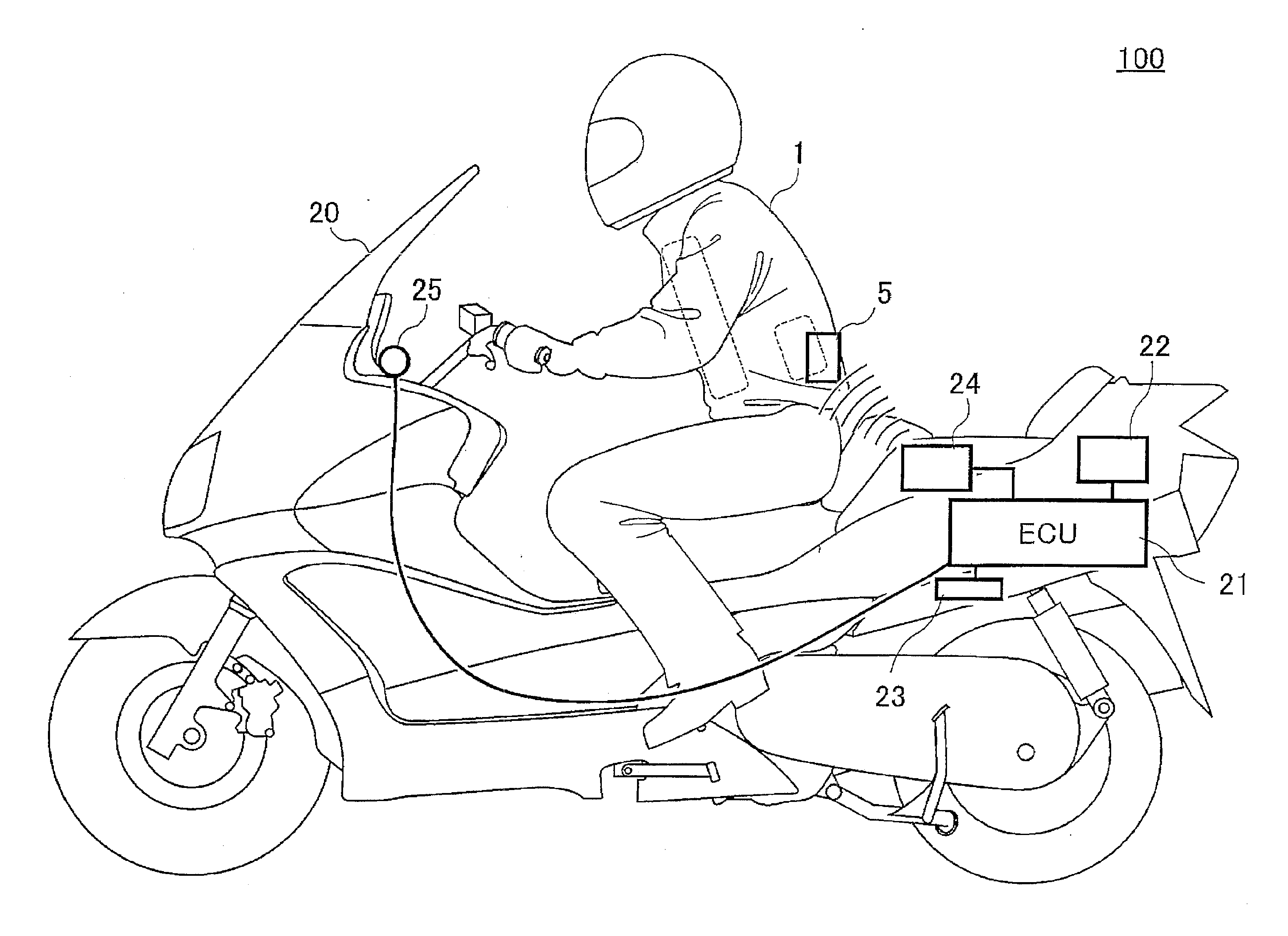
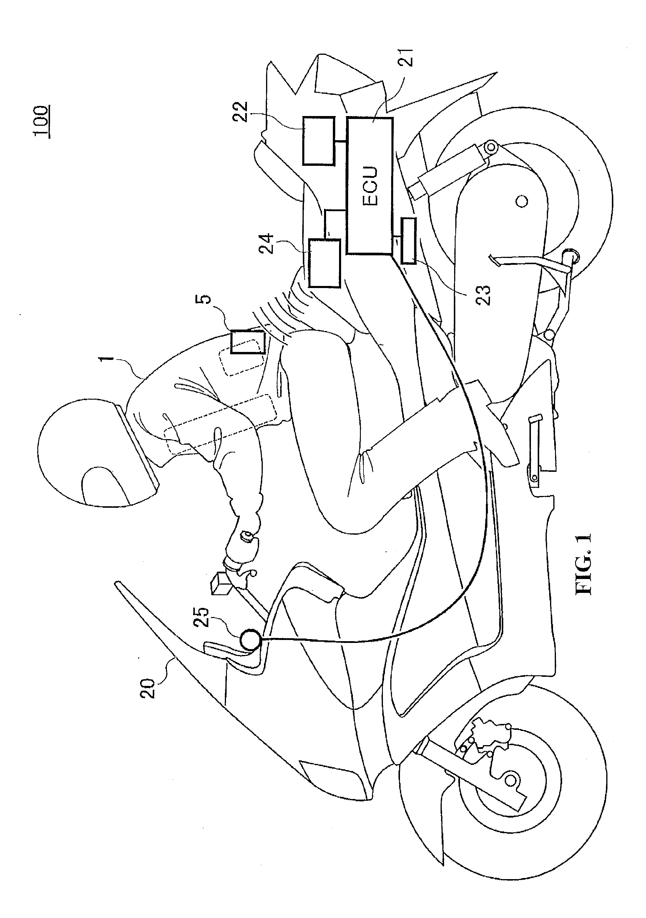
[0035]FIG. 1 is a schematic diagram showing a configuration of an airbag jacket activating system 100 according to the first embodiment.

[0036]The airbag jacket activating system 100 includes a motorcycle 20 as a vehicle and an airbag jacket 1 which a rider of the motorcycle 20 wears.

[0037]The motorcycle 20 includes an ECU (Electronic Control Unit) 21 as a control unit; a battery 22 configured to supply electric power; an acceleration sensor 23 (acceleration detecting means) configured to detect an acceleration of the motorcycle 20; a radio transceiver 24 configured to make radio communications with the airbag jacket 1 and an indicator 25. In addition, the battery 22, the acceleration sensor 23 and the radio transceiver 24 are connected to the ECU 21. Note that, as described later, the radio transceiver 24 includes an RF transceiver 24a configured to make radio communications with ...

third embodiment

[0114]With regard to the third embodiment, in the motorcycle 20, the control unit 213 transmits the same data through the RF transceiver 24a by use of multiple frequencies in the RF band. In addition, in the airbag jacket 1, the control unit 33 deploys the airbag when succeeding in the collation of the RF communications ID at a predetermined or higher rate over the multiple frequencies, more specifically, at the majority of the multiple frequencies and receives the ignition signal together. Hereinbelow, for the purpose of making the descriptions simple, let us assume that the multiple frequencies are three frequencies f1, f2, f3.

[0115]FIG. 9 is a flowchart showing a process of the control unit 213 on the motorcycle 20 according to this embodiment. The processing through the LF communications of the LF transceiver 24b in the first embodiment is omitted.

[0116]In step S61, the control unit 213 judges whether or not a predetermined or larger external force is applied on the basis of the...


PUM


Abstract

An airbag jacket activating system includes radio communications transceivers configured to make RF communications and LF communications, respectively. An acceleration sensor configured to detect acceleration of a motorcycle. An update unit configured to update an LF communications ID, to code the updated LF communications ID together with an RF communications ID, and to transmit the coded updated LF communications ID and the coded RF communications ID to an airbag jacket through RF communications. An update unit configured to store the updated LF communications ID in a case where the LF communications ID is received together with the RF communication ID. A control unit configured to cause the coded RF communications ID and an ignition signal to be transmitted through the RF communications, and to cause the LF communications ID and the ignition signal to be transmitted through the LF communications when the acceleration exceeds a predetermined value;

Description

CROSS-REFERENCE TO RELATED APPLICATIONS[0001]The present application claims priority under 35 USC 119 to Japanese Patent Application No. 2010-068653 filed on Mar. 24, 2010 the entire contents of which are hereby incorporated by reference.BACKGROUND OF THE INVENTION[0002]1. Field of the Invention[0003]The present invention relates to an airbag jacket activating system. More specifically, the present invention relates to an airbag jacket activating system configured to make radio communications with a vehicle.[0004]2. Description of Background Art[0005]Keyless entry systems configured to carry out locking and unlocking operations through radio communications with a portable transceiver have been heretofore used for vehicles such as automobiles and motorcycles. For example, Japanese Patent Application Publication No. 2006-22606 discloses a keyless entry system in which a low-frequency (LF) request signal is transmitted from a vehicle to a portable transceiver and once the portable tran...

Claims


Application Information

Patent Timeline
Patent Type & Authority Applications(United States)
IPC IPC(8): H04W4/00A41D13/015B60R21/013B60R21/16B60R25/01B60R25/04B62J27/00
CPCA41D13/018B62J27/00B60R2021/0088B60R21/0132B62J27/20
Inventor KOJIMA, HIROYUKIOGAWA, SUMITAKA
Owner HONDA MOTOR CO LTD
Learn More