Power transmitting apparatus

a power transmitting apparatus and power technology, applied in the direction of mechanical actuated clutches, mechanical apparatus, clutches, etc., can solve the problems the loss of some power transmitting efficiency, and the inability to reliably perform the ineffective stroke reducing control, so as to achieve the effect of reducing the starting performan

Inactive Publication Date: 2011-09-29
FCC KK
View PDF9 Cites 6 Cited by
  • Summary
  • Abstract
  • Description
  • Claims
  • Application Information

AI Technical Summary

Benefits of technology

In embodiments where the ineffective stroke reducing control is performed based on the slip ratio calculated by the slip ratio calculating device for the first clutch device or the slip ratio calculating device for the torque converter, it is possible to more precisely and reliably perform the ineffective stroke reducing control relative to the first clutch device.
In embodiments where the slip ratio of the second clutch device is calculated from the difference or the ratio between the rotational speed measured by the input-side measuring device for the second clutch device and the rotational speed measured by the output-side measuring device for the second clutch device, it is possible to assume the coefficient of friction of the second clutch device based on the slip ratio and thus to easily and more precisely perform the clutch control relative to the second clutch device.
In embodiments including the selecting device for transmitting the driving force of the driving source to the wheels through the power transmitting system of the torque converter or for transmitting the driving force of the driving source to the wheels without through the power transmitting system of the torque converter by properly selecting operation of the first clutch device or the second clutch device in accordance with conditions of the vehicle on its forward run including the starting-up, it is possible to suppress complication and size increase of the power transmitting apparatus, to improve the starting-up performance because of the torque amplifying function of the torque converter, and also to improve power transmitting efficiency during the steady run of vehicle.
In embodiments where the control of hydraulic oil of the second clutch device is performed based on the slip ratio calculated by the slip ratio calculating device for the second clutch device, it is possible to more precisely perform the control of hydraulic oil of the second clutch device.
In embodiments where the operation of the second clutch device is prevented at low temperatures, it is possible to exclusively use the first clutch device rather than the second clutch device, the performance of which can be deteriorated in responsiveness because of low temperatures and thus to suppress the deterioration of responsiveness of the power transmitting apparatus.
In embodiments where the operation of the second clutch device is limited at low temperatures, it is possible to preferentially use the first clutch device rather than the second clutch device the performance of which can be deteriorated in responsiveness because of low temperatures and thus to suppress the deterioration of responsiveness of the power transmitting apparatus.

Problems solved by technology

More specifically, during steady operation of a vehicle having a torque converter type system, although it has a technical merit of improving the starting performance because of the torque amplifying function of the torque converter when movement is initially started, it can suffer from loss of some power transmitting efficiency because of slippage generated in the torque converter e.g. during steady run of a vehicle.
On the other hand, in the clutch type system, although it has a technical merit of improving the power transmitting efficiency because of not having any slippage which would be found in the torque converter e.g. during steady run of vehicle, it has a technical demerit of decreasing the starting performance since it does not have the torque amplifying function on start of a vehicle obtained by the torque converter.
Further, the known system described in Japanese Laid-open Patent Publication No. 3193 / 2005, which is a combined torque converter and clutch type, is a relatively large and complicated structure in which the lock-up clutch is movable between the connected position and the non-connected position in the hydraulic atmosphere within the torque converter.
This increases both the manufacturing cost and the maintenance cost.

Method used


Image

  • Power transmitting apparatus
  • Power transmitting apparatus
  • Power transmitting apparatus

Examples


Embodiment Construction

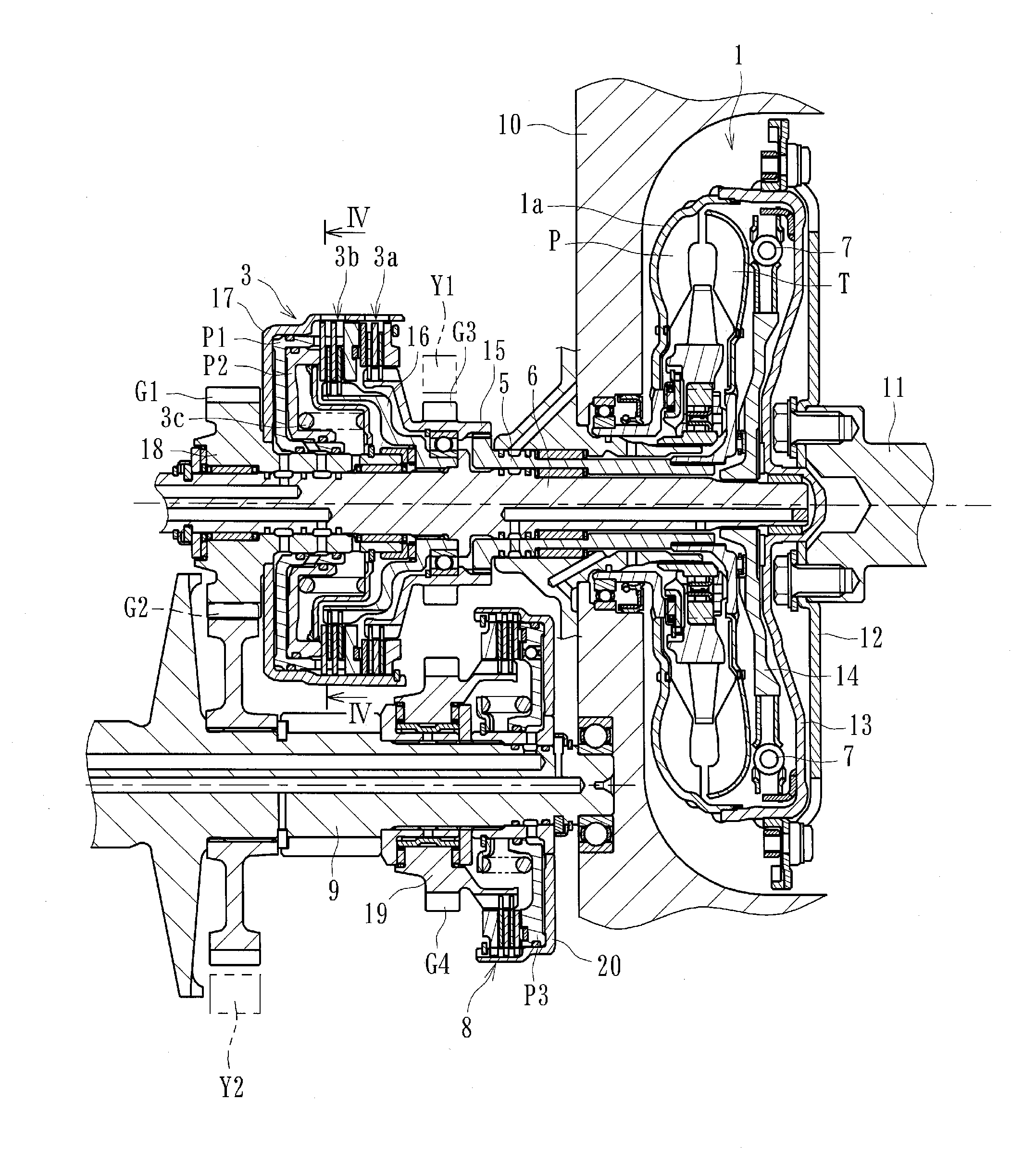
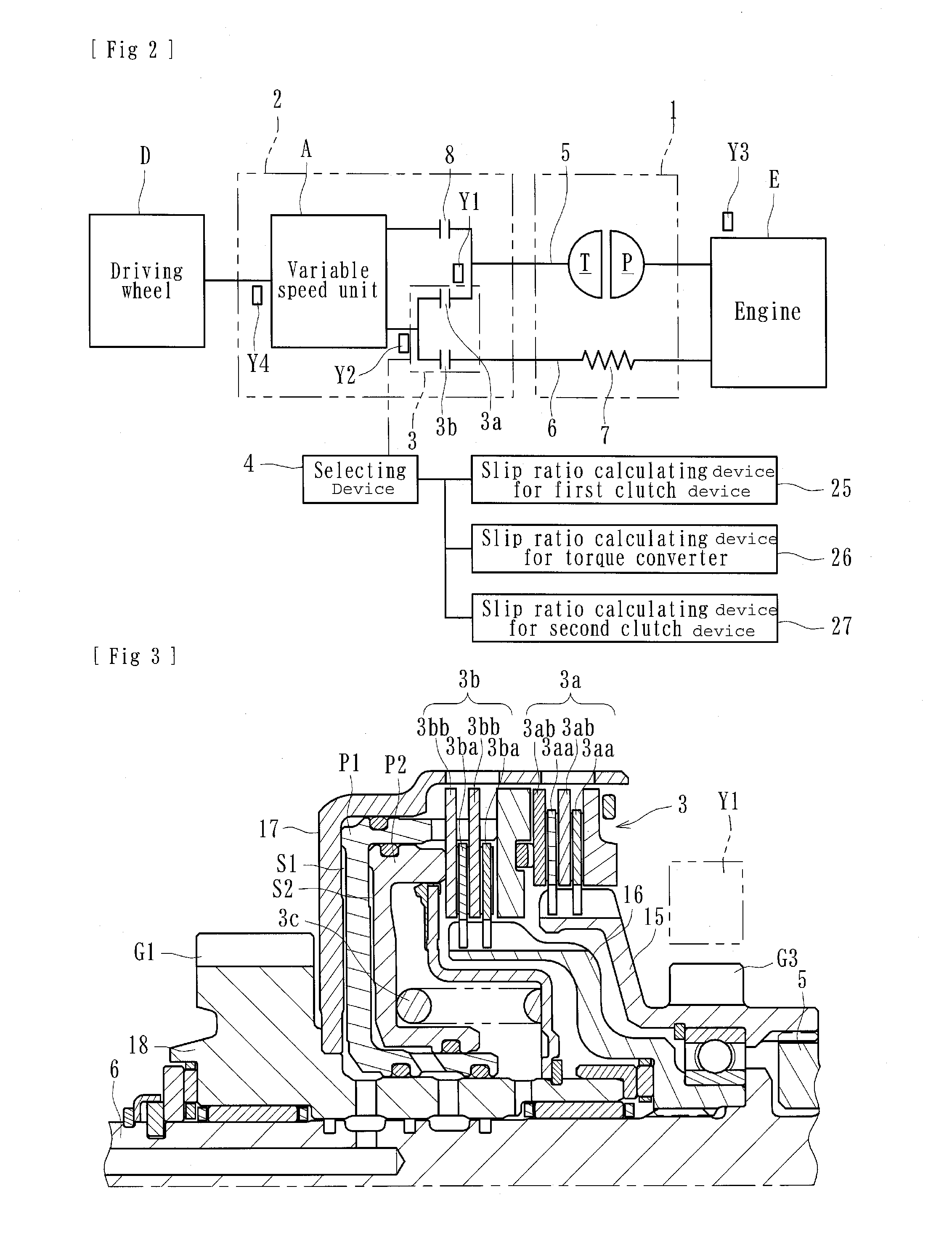
An embodiment of a power transmitting apparatus can be configured to transmit or cut-off the driving force from an engine (driving source) of an automobile (vehicle) to or from the wheels (driving wheels). Such an apparatus can include, with reference to FIGS. 1 and 2, a torque converter 1, a clutch mechanism 3, a selecting device 4, a first driving shaft 5, a second driving shaft 6, a damper mechanism 7, a third clutch device 8, a slip ratio calculating device 25 for a first clutch device, a slip ratio calculating device 26 for the torque converter, and a slip ratio calculating device 27 for a second clutch device.

An embodiment of a power transmitting can further comprise a speed sensor Y1 which can serve as an “input-side measuring means”, a speed sensor Y2 which can serve as an “output-side measuring means”, a speed sensor Y3 which can serve as an “input-side measuring means for the second clutch device”, and a speed sensor Y4 configured to detect a speed of a vehicle. The above ...


PUM


Abstract

A power transmitting apparatus, such an automotive transmission, adapted to properly select transmission of or cutting-off of a driving force of the driving source to or from the wheels of a vehicle can include a torque converter having a torque amplifying function. A clutch mechanism can include a first clutch device configured to transmit the driving force to the wheels through the torque converter and a second clutch device configured to transmit the driving force without passing through the torque converter. A selecting device can control the first clutch device or the second clutch device in accordance with conditions of the vehicle including starting from a stop. An input-side measuring device can be used to measure an input-side rotational speed of the first clutch device and an output-side measuring device can be used for measuring an output-side rotational speed of the first clutch device. A slip ratio calculating device can be used to calculate the slip ratio of the first clutch device from the difference or the ratio between the rotational speed measured by the input-side measuring device and the rotational speed measured by the output-side measuring device.

Description

BACKGROUND OF THE INVENTIONS1. Field of the InventionsThe present inventions relate to power transmitting apparatuses, such as vehicle transmissions, which transmit power from a driving source of a vehicle to the wheels of the vehicle and which are adapted to properly select transmission of power and cutting-off of power to or from the wheels.2. Description of the Related ArtTwo types of known power transmitting apparatuses for vehicles (e.g., “automatic transmissions”) provide starting power (power for initiating movement of the vehicle from a stop) in different ways. One type uses a torque converter (“torque converter type”) and another type uses a starting clutch (“starting clutch type”) to provide starting power used to start the movement of the vehicle from a stop. In the torque converter type devices, the starting performance benefits from the torque amplifying function of the torque converter. On the other hand, the starting clutch type benefits from increased efficiency beca...

Claims


Application Information

Patent Timeline
Patent Type & Authority Applications(United States)
IPC IPC(8): B60W10/10B60W30/18F16H61/02
CPCF16D21/06Y10T477/6388F16D2021/063F16D2021/0661F16D2500/1086F16D2500/30402F16D2500/30406F16D2500/50224F16D2500/70406F16H61/143F16H2059/467F16H2061/145Y10T477/63385Y10T477/6395Y10T477/6414F16D48/08F16D25/10
Inventor OHASHI, TATSUYUKIASATSUKE, SHOUJIOISHI, AKIOCHIBA, RYOUHEIISHIMURA, JUNISHIKAWA, KEIICHI
Owner FCC KK
Why Eureka
Try Eureka