Medical image diagnosis assisting apparatus and method, and computer readable recording medium on which is recorded program for the same

a technology of medical image and recording medium, which is applied in the field of medical image diagnosis assisting apparatus and method, and the recording of program on the same computer readable recording medium, can solve the problems of possible metastasis and portion of the lesion

Active Publication Date: 2011-09-29
FUJIFILM CORP
View PDF11 Cites 22 Cited by
  • Summary
  • Abstract
  • Description
  • Claims
  • Application Information

AI Technical Summary

Benefits of technology

[0032]According to the present invention, from a three-dimensional medical image representing a subject's internal structure having a branch structure and a peripheral structure, an abnormal peripheral structure is detected and the branch structure is extracted. Then, an associated branch structure functionally associated with the abnormal peripheral structure is identified based on position information of each point in the extracted branch structure and an associated peripheral structure functionally associated with the identified associated branch structure. Consequently, the associated peripheral structure includes a structure functionally associated with the associated branch structure adjacent to the abnormal peripheral structure, indicating a necessary and sufficient area as the treatment target area for the abnormal peripheral structure. Thus, the invention may contribute to an appropriate and easy decision of the treatment policy for the abnormal peripheral structure based on the associated peripheral structure.

Problems solved by technology

On the other hand, if the target area is not large enough, a portion of the lesion may remain and a metastasis may possibly occur.
The method described in each of Non-patent Documents, however, only detects an abnormal area in lung fields and the documents do not describe at all how to assist in determining the treatment target area when a certain treatment needs to be performed on the abnormal area.

Method used


Image

  • Medical image diagnosis assisting apparatus and method, and computer readable recording medium on which is recorded program for the same
  • Medical image diagnosis assisting apparatus and method, and computer readable recording medium on which is recorded program for the same
  • Medical image diagnosis assisting apparatus and method, and computer readable recording medium on which is recorded program for the same

Examples


first embodiment

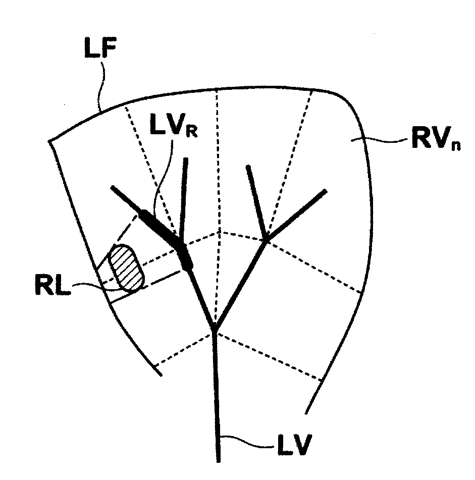
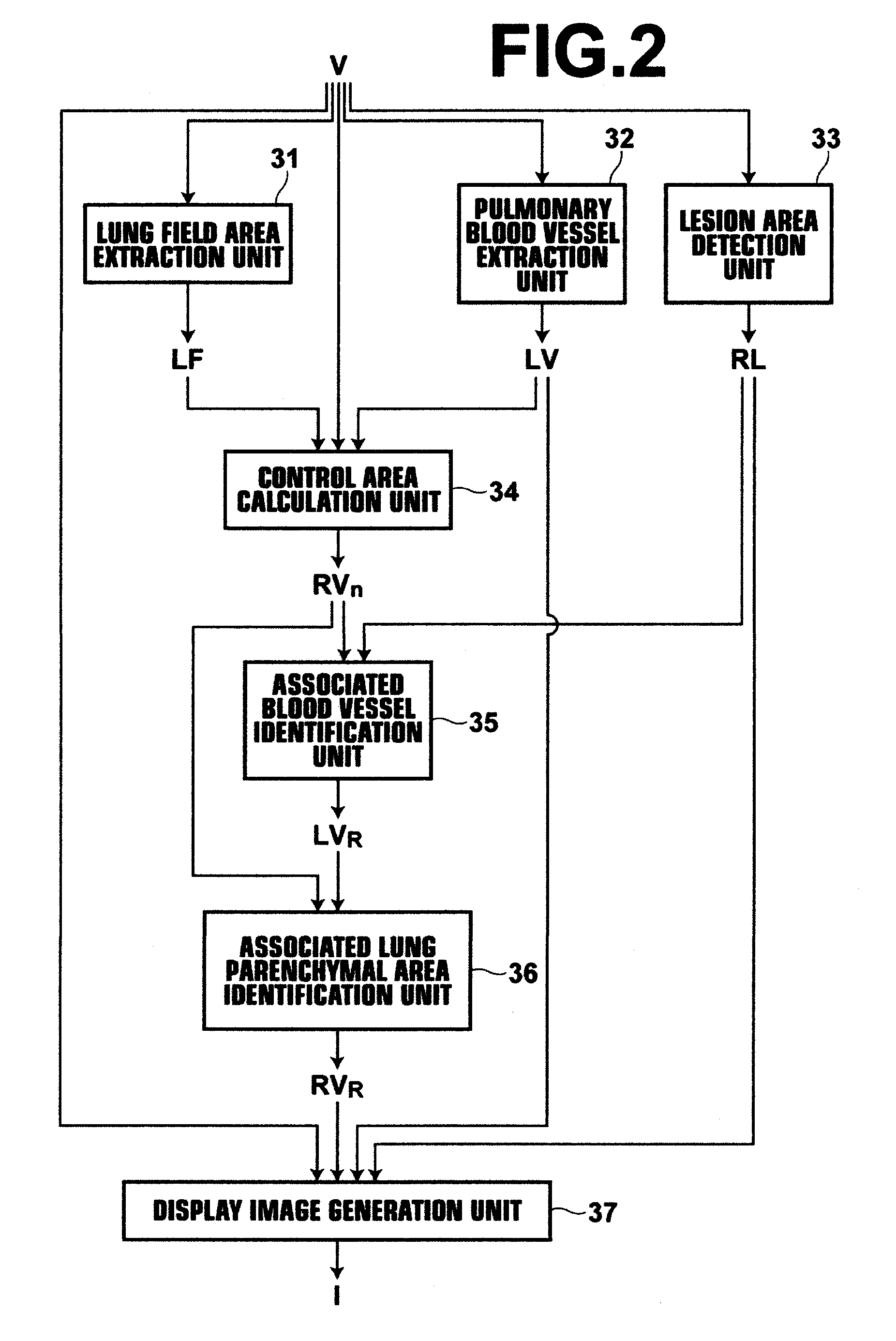
[0069]In the present invention, an associated lung parenchymal area RVR functionally associated with a pulmonary blood vessel structure located in the distal side of the associated pulmonary blood vessel structure LVR is identified by the series of process steps described above. The associated lung parenchymal area RVR represents a necessary and sufficient area as the target area for treating the lesion area RL, so that treatment policy for the lesion area RL can be determined appropriately and easily based on the associated lung parenchymal area RVR.

[0070]In the embodiment described above, the description has been made on the assumption that an associated pulmonary blood vessel structure LVR is also removed with the resection of a lesion area RL. But associated lung parenchymal area identification unit 36 may be a unit that identifies a lung parenchymal area associated only with an associated pulmonary blood vessel structure LVR associated with a lesion area RL as the associated lu...

second embodiment

[0074]In the present invention, lesion area enlargement unit 38 enlarges a lesion area RL of a size when detected by lesion area detection unit 33 and an associated pulmonary blood vessel structure LVR and an associated lung parenchymal area RVR are identified based on the enlarged lesion area RL′. This allows the treatment target area for the lesion to be considered by predicting the growth of the lesion area RL.

[0075]Further, the growth condition EC can be defined in a reference table with respect to each of a plurality of time points according to the elapsed time from the present time. In this case, in the flowchart of FIG. 10, steps #5.1 to #7 are repeated by the number corresponding to the plurality of time points. FIGS. 11A to 11C schematically illustrate display images, each representing a lesion area and an associated lung parenchymal area at each of a plurality of time points. FIG. 11A shows the state of present time t1, FIG. 11B shows the state of present time t2, and FIG....

third embodiment

[0086]As described above, in the present invention, intersection point detection unit 40 detects an intersection point PIn between the associated lung parenchymal area RVR and pulmonary vein structure VV or bronchus structure BR. When resecting an associated lung parenchymal area RVR including a lesion area RL, this allows a point to be sutured or inosculated on the pulmonary vein or bronchi to be understood easily.

[0087]Further, in the lung parenchyma, gas exchange in the blood occurs with both the pulmonary artery and pulmonary vein. Therefore, if both the pulmonary artery and pulmonary vein are extracted by pulmonary blood vessel extraction unit 32 without distinction and a control area is calculated by control area calculation unit 34 using both the pulmonary artery and pulmonary vein, as in the first embodiment, the lung parenchymal area is divided into a control area controlled by the pulmonary artery and a control area controlled by the pulmonary vein, resulting in a division...


PUM


Abstract

A lesion area detection unit detects an abnormal peripheral structure (lesion area), a pulmonary blood vessel extraction unit extracts a branch structure (pulmonary blood vessel) from the three-dimensional medical image, an associated blood vessel identification unit identifies an associated branch structure functionally associated with the abnormal peripheral structure based on position information of each point in the extracted branch structure, and an associated lung parenchymal area identification unit identifies an associated peripheral area (lung parenchyma) functionally associated with the identified associated branch structure based on the position information of each point in the extracted branch structure.

Description

BACKGROUND OF THE INVENTION[0001]1. Field of the Invention[0002]The present invention relates to an apparatus and method for assisting image diagnosis using a three-dimensional medical image representing a subject's internal structure constituted by branch and peripheral structures, such as a lung. The invention also relates to a computer readable recording medium on which is recorded a program for the same.[0003]2. Description of the Related Art[0004]As a technology for assisting image diagnosis using a three-dimensional medical image representing a chest obtained by a CT device, a technology that automatically detects an abnormal opacity, such as lung cancer and the like, from the three-dimensional medical image is known.[0005]For example, a method of detecting lung cancer opacity from a three-dimensional CT image representing a chest using a two-dimensional N-Quoit filter, a variable neighborhood type Laplacian filter, a Min-DD filter, and a contrast filter, each extended to thre...

Claims


Application Information

Patent Timeline
Patent Type & Authority Applications(United States)
IPC IPC(8): A61B6/03
CPCG06T7/0012G06T7/0079G06T2207/10072G06T2207/30101G06T2207/30056G06T2207/30061G06T2207/30096G06T2207/20141G06T7/10G06T7/187
Inventor MIZUNO, OSAMU
Owner FUJIFILM CORP
Why Eureka
Try Eureka