
Apparatus for Detecting Angular Velocity and Acceleration

Inactive Publication Date: 2011-09-29
HITACHI AUTOMOTIVE SYST LTD
View PDF11 Cites 16 Cited by
  • Summary
  • Abstract
  • Description
  • Claims
  • Application Information

AI Technical Summary

Benefits of technology

[0006]By outputting the sensor outputs and the diagnostic results together in response to a single transmission demand from the external device, the time for the transmission of required information can be shortened. Further, by adding the error detection code to the sensor outputs when the sensor outputs are transmitted to the external device, the externa

Problems solved by technology

Furthermore, since all the diagnostic processes with respect to the sensors are executed by the DSP, the execution of error diagnosis by the DSP makes unnecessary the failure diagnoses of individual diagnosing functions themselves.

Method used


Image

  • Apparatus for Detecting Angular Velocity and Acceleration
  • Apparatus for Detecting Angular Velocity and Acceleration
  • Apparatus for Detecting Angular Velocity and Acceleration

Examples


Embodiment Construction

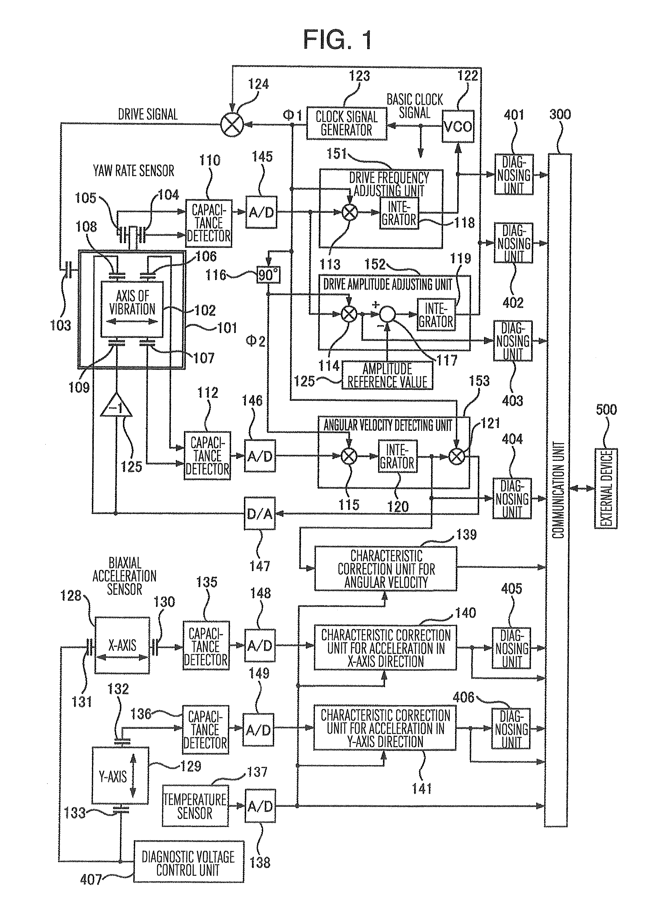
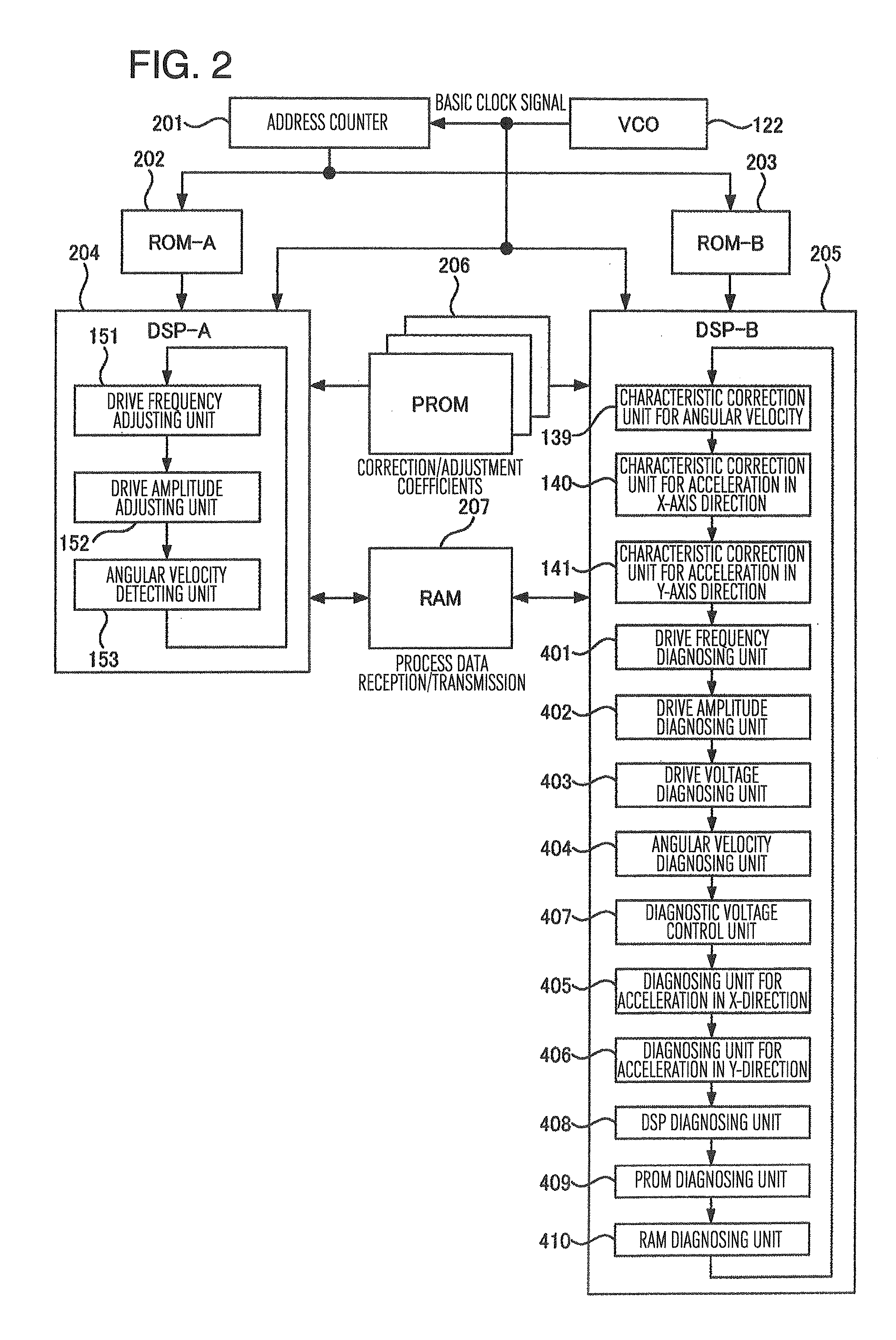
[0018]An embodiment of this invention will be described with reference to FIGS. 1˜9.

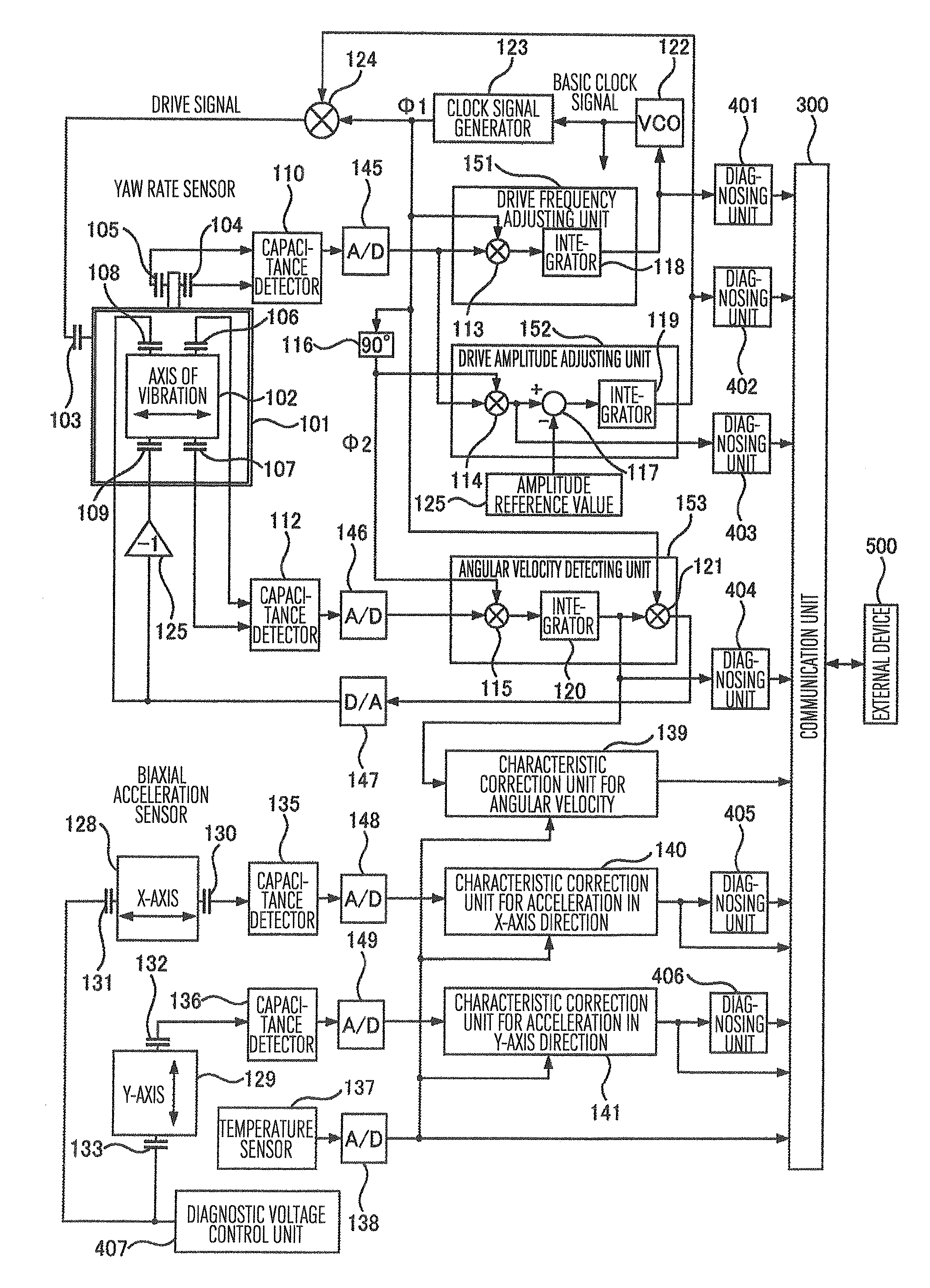
[0019]FIG. 1 shows in block diagram a control circuit for an angular velocity sensor (yaw rate sensor) and an acceleration sensor (biaxial acceleration sensor), as an embodiment of this invention. An angular velocity detection element 101 includes a vibrator 102 which has a predetermined mass and vibrates at a predetermined frequency fd in the direction along the axis of vibration; a fixed electrode (external force application unit) 103 which generates electrostatic force for adjusting the amplitude of the vibration of the vibrator 102 along the axis of vibration and the vibrating frequency of the vibrator 102; electrodes 104 and 105 (displacement detection unit) for detecting the amplitude of the vibration of the vibrator 102 and the vibrating frequency of the vibrator 102 as changes in electrostatic capacitances; fixed electrodes 106 and 107 (displacement detection unit) for detecting as change in ...


PUM


Abstract

An apparatus for detecting angular velocity and acceleration having diagnosing units for diagnosing the function of detecting angular velocity; diagnosing units for diagnosing the function of detecting acceleration; a diagnosing unit for a DSP or a MPU; multiple ROMs storing the same data; a diagnosing unit for the ROMs; a diagnosing unit for a RAM; a unit for outputting the outputs of the angular velocity sensor, the acceleration sensor and the results of diagnoses all together in response to an output command from an external device; and a unit for sending error detection codes along with the sensor outputs and the result of diagnoses when the sensor outputs and the results of diagnoses are outputted together.

Description

BACKGROUND OF THE INVENTION[0001]The present invention relates to an apparatus having the self-diagnosing function and capable of detecting angular velocity and acceleration.[0002]Examples of the function of diagnosing an angular velocity sensor of vibration type are embodied as apparatuses disclosed in the specifications of Japanese Patent Nos. 4311496 and 3991978.[0003]If a sensor for detecting the angular velocity and acceleration of an automobile necessary to secure the driving safety must be placed in the environment such as the engine room where the range of temperature change is wide and the influence by vibrations and electromagnetic noise is considerable, it is vital to make the reliability of the sensor sufficiently high. To meet this requirement, Japanese Patent No. 4311496, discloses the mechanism wherein the angular velocity, the acceleration and the error-diagnosis signal at the same time point are digitally outputted in the time-division manner by an output circuit, a...

Claims


Application Information

Patent Timeline
IPC IPC(8): G01C19/56G01C19/5726G01P15/125G08C25/00
CPCG01C19/56G01C25/00G01C19/5776G01P15/18G01P21/00G01P15/08
Inventor NAKAMURA, TOSHIAKIMATSUMOTO, MASAHIROASANO, SATOSHI
Owner HITACHI AUTOMOTIVE SYST LTD
Learn More